Removal Procedure
- Raise the vehicle. Refer to Lifting and Jacking the Vehicle in General Information.
- Remove the fuel tank filler cap.
- Remove the protective shield.
- Open the air bleed valve on top of the fuel manager/filter in order to release any of the pressure in the fuel supply system.
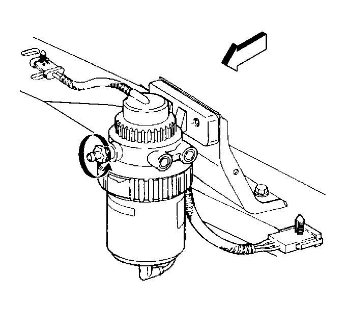
- Remove water-in-fuel senor connector at bottom of filter.
- Drain the filter by attaching a flexible tube or hose 6.35-7.74 mm (1/4 to 5/16 in) ID to the water drain valve.
- Slowly open the water drain valve. The drain does not have to be totally removed for fuel to drain.
- Turn the locking ring in a counterclockwise direction. If unable to turn by hand, use a strap wrench (oil filter type) in order to break the element nut loose.
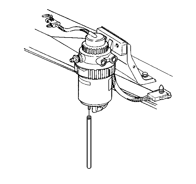
- Remove the element by pulling straight down.
- Remove the water-in-fuel sensor from the element.
Installation Procedure
Important: The new element is not equipped with a water-in-fuel sensor, only a plug. The water-in-fuel sensor/valve must be removed form the old element. Use the new seal, attached to the plug, to replace the old seal on the water-in-fuel sensor/valve.
Make sure that the mating surface between the element assembly and the filter assembly is clean before installation.- Install water-in-fuel sensor valve with new seal.
- Install the new element by aligning the arrow on the element to the air bleed drain valve on header assembly.
- Push the element in a upward direction until the mating surfaces make contact.
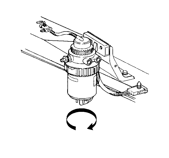
- Align the locking ring on the filter header assembly.
- Install the connector on the water-in-fuel sensor/valve.
- Reinstall the fuel tank filler cap.
- Install the protective shield.
- Bleed the air from the fuel manager/filter.
- Lower the vehicle.
Notice: Use the correct fastener in the correct location. Replacement fasteners must be the correct part number for that application. Fasteners requiring replacement or fasteners requiring the use of thread locking compound or sealant are identified in the service procedure. Do not use paints, lubricants, or corrosion inhibitors on fasteners or fastener joint surfaces unless specified. These coatings affect fastener torque and joint clamping force and may damage the fastener. Use the correct tightening sequence and specifications when installing fasteners in order to avoid damage to parts and systems.
Tighten
Tighten the locking ring securely by hand. A clicking noise will be
heard, and the arrow on the locking ring will be aligned with the arrow on
the element.
