Removal Procedure
- Disable the SIR system. Refer to Disabling the SIR System in SIR.
- Remove the steering wheel. Refer to Steering Wheel Replacement .
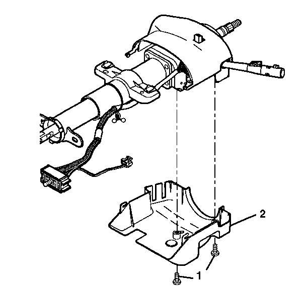
- Remove the 2 pan head tapping screws (1) from the lower shroud (2).
- Tilt the lower shroud down.
- Slide the lower shroud backward in order to disengage the locking tabs.
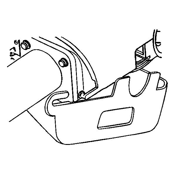
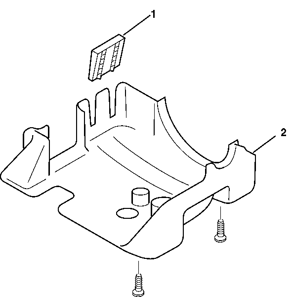
- Remove the shroud protector (1) from the lower shroud (2).
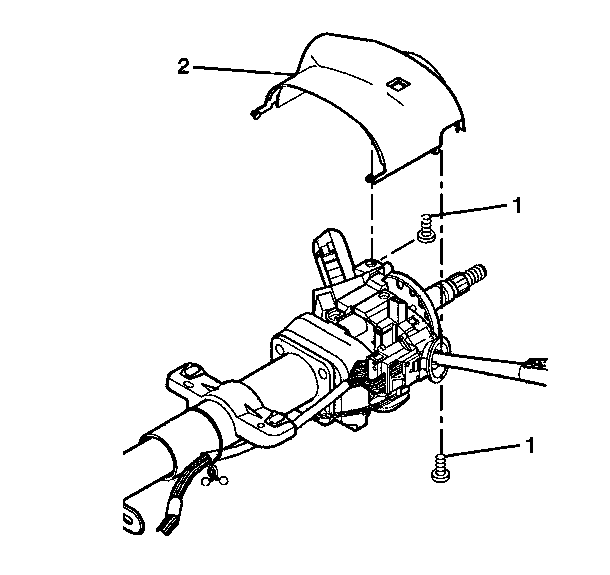
- Remove the 2 TORX® head screws (1) from the upper shroud (2).
- Remove the ignition lock cylinder. Refer to Ignition Lock Cylinder Replacement - On Vehicle .
- Remove the upper shroud (2) from the steering column.
Caution: This vehicle is equipped with a Supplemental Inflatable Restraint (SIR) System. Failure to follow the correct procedure could cause the following conditions:
• Air bag deployment • Personal injury • Unnecessary SIR system repairs • Refer to SIR Component Views in order to determine if you are performing service on or near the SIR components or the SIR wiring. • If you are performing service on or near the SIR components or the SIR wiring, disable the SIR system. Refer to Disabling the SIR System.
Remove the lower shroud from the upper shroud.
Installation Procedure
- Install the upper shroud (2) onto the steering column.
- Install the ignition lock cylinder. Refer to Ignition Lock Cylinder Replacement - On Vehicle .
- Screw the 2 TORX® head screws (1) into the upper shroud (2).
- Install the shroud protector (1) onto the lower shroud (2).
- Install the lower shroud onto the upper shroud.
- Match the tab slots on the lower shroud with the locking tabs on the upper shroud.
- Tilt the lower shroud up.
- Slide the lower shroud forward until the locking tabs snap into the tab slots.
- Screw the 2 pan head tapping screws (1) into the lower shroud (2).
- Install the steering wheel. Refer to Steering Wheel Replacement .
- Enable the SIR system. Refer to Disabling the SIR System in SIR.
Notice: Use the correct fastener in the correct location. Replacement fasteners must be the correct part number for that application. Fasteners requiring replacement or fasteners requiring the use of thread locking compound or sealant are identified in the service procedure. Do not use paints, lubricants, or corrosion inhibitors on fasteners or fastener joint surfaces unless specified. These coatings affect fastener torque and joint clamping force and may damage the fastener. Use the correct tightening sequence and specifications when installing fasteners in order to avoid damage to parts and systems.
Tighten
Tighten the 2 TORX® head screws to 1.4 N·m (12 lb in).
Important: The shift lever seal must be seated in the shrouds.
Tighten
Tighten the 2 pan head tapping screws to 3.5 N·m
(31 lb in).
