Fuel Hose/Pipes Replacement - Chassis Engine to Fuel Filter
Removal Procedure
- Disconnect the negative battery cable.
- Relieve the fuel system pressure. Refer to Fuel Pressure Relief .
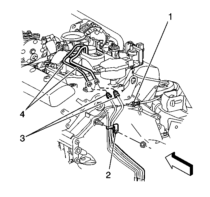
- Disconnect the fuel feed and return pipes (3) from the engine compartment fuel pipes (4).
- Remove the fuel pipes from the bellhousing stud retainer clip (2).
- Raise the vehicle. Refer to Lifting and Jacking the Vehicle in General Information.
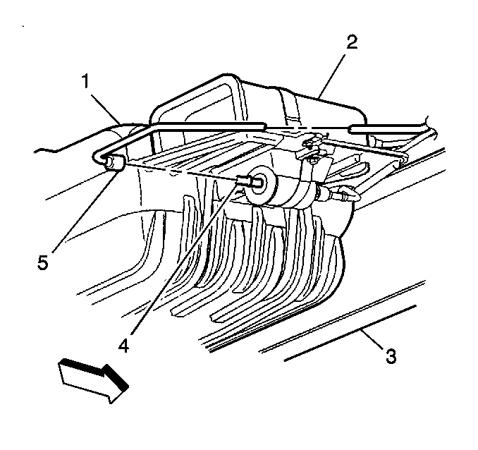
- Disconnect the fuel feed pipe (5) at the fuel filter.
- Disconnect the chassis fuel return pipe (4) at the rear fuel return pipe (3).
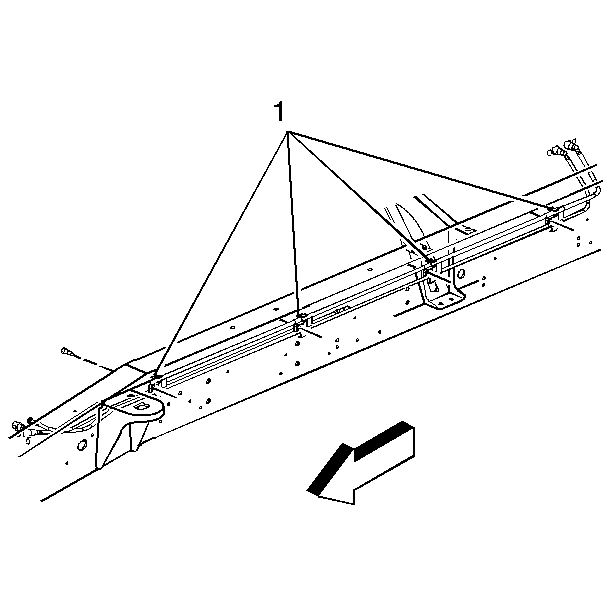
- Remove the fuel pipe retaining clips (1). Note the location of the retaining clips for installation.
- Remove the fuel feed and return pipes (2).
Caution: Unless directed otherwise, the ignition and start switch must be in the OFF or LOCK position, and all electrical loads must be OFF before servicing any electrical component. Disconnect the negative battery cable to prevent an electrical spark should a tool or equipment come in contact with an exposed electrical terminal. Failure to follow these precautions may result in personal injury and/or damage to the vehicle or its components.
Installation Procedure
- Position the fuel feed and return pipes (2) in the vehicle.
- Install the fuel pipe retaining clips (1).
- Connect the chassis fuel return pipe (4) to the rear fuel return pipe (3).
- Connect the fuel feed pipe (5) to the fuel filter.
- Lower the vehicle.
- Connect the fuel feed and return pipes (3) to the engine compartment fuel pipes (4).
- Install the fuel pipes to the retainer clip (2).
- Tighten the fuel filler cap.
- Connect the negative battery cable.
- Inspect for leaks:
- Install the engine cover. Refer to Engine Cover Replacement in Interior Trim.
Notice: Use the correct fastener in the correct location. Replacement fasteners must be the correct part number for that application. Fasteners requiring replacement or fasteners requiring the use of thread locking compound or sealant are identified in the service procedure. Do not use paints, lubricants, or corrosion inhibitors on fasteners or fastener joint surfaces unless specified. These coatings affect fastener torque and joint clamping force and may damage the fastener. Use the correct tightening sequence and specifications when installing fasteners in order to avoid damage to parts and systems.
Tighten
Tighten the bolts to 12 N·m (106 lb in).
Ensure the O-rings are in place
Tighten
Tighten the fuel pipe fittings to 27 N·m (20 lb ft)
using a backup wrench.
Tighten
Tighten the fuel pipe retainer clip nut to 28 N·m (21 lb
ft).
| 10.1. | Turn ON the ignition for 2 seconds. |
| 10.2. | Turn OFF the ignition for 10 seconds. |
| 10.3. | Turn ON the ignition. |
| 10.4. | Inspect for fuel leaks. |
Fuel Hose/Pipes Replacement - Chassis Filter to Tank Cutaway Van Side Tank
Removal Procedure
- Disconnect the negative battery cable.
- Relieve the fuel system pressure. Refer to Fuel Pressure Relief .
- Drain the fuel tank. Refer to Fuel Tank Draining .
- Remove the fuel tank. Refer to Fuel Tank Replacement .
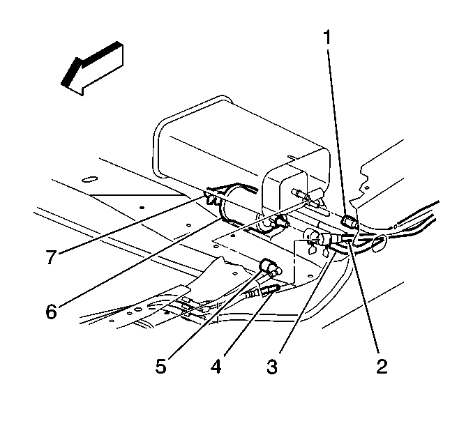
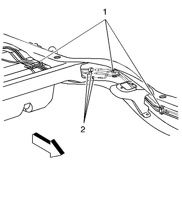
- Disconnect the fuel feed pipe (7) at the fuel filter (6).
- Disconnect the chassis fuel return pipe (4) at the rear fuel return pipe (2).
- Remove the fuel pipe retaining clips (1).
- Remove the fuel feed and return pipes.
Caution: Unless directed otherwise, the ignition and start switch must be in the OFF or LOCK position, and all electrical loads must be OFF before servicing any electrical component. Disconnect the negative battery cable to prevent an electrical spark should a tool or equipment come in contact with an exposed electrical terminal. Failure to follow these precautions may result in personal injury and/or damage to the vehicle or its components.
Installation Procedure
- Install the fuel feed and return pipes and the fuel pipe retaining clips (1).
- Connect the chassis fuel return pipe (4) to the rear fuel return pipe (2).
- Connect the fuel feed pipe (7) to the fuel filter (6).
- Install the fuel tank. Refer to Fuel Tank Replacement .
- Lower the vehicle.
- Refill the fuel tank.
- Tighten the fuel filler cap.
- Connect the negative battery cable.
- Inspect for leaks:
- Install the engine cover. Refer to Engine Cover Replacement in Interior Trim.
Notice: Use the correct fastener in the correct location. Replacement fasteners must be the correct part number for that application. Fasteners requiring replacement or fasteners requiring the use of thread locking compound or sealant are identified in the service procedure. Do not use paints, lubricants, or corrosion inhibitors on fasteners or fastener joint surfaces unless specified. These coatings affect fastener torque and joint clamping force and may damage the fastener. Use the correct tightening sequence and specifications when installing fasteners in order to avoid damage to parts and systems.
Tighten
Tighten the bolts to 12 N·m (106 lb in).
| 9.1. | Turn ON the ignition for 2 seconds. |
| 9.2. | Turn OFF the ignition for 10 seconds. |
| 9.3. | Turn ON the ignition. |
| 9.4. | Inspect for fuel leaks: |
Fuel Hose/Pipes Replacement - Chassis Filter to Tank Cutaway Van Rear Tank
Removal Procedure
- Disconnect the negative battery cable.
- Relieve the fuel system pressure. Refer to Fuel Pressure Relief .
- Drain the fuel tank. Refer to Fuel Tank Draining .
- Raise the vehicle. Refer to Lifting and Jacking the Vehicle in General Information.
- Disconnect the fuel feed pipe (7) at the fuel filter (6).
- Disconnect the chassis fuel return pipe (4) at the rear fuel return pipe (2).
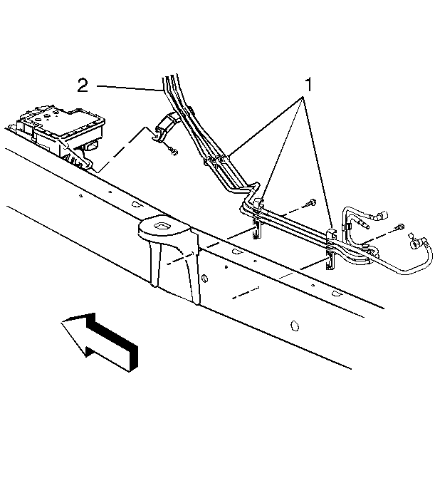
- Disconnect the chassis fuel feed and return pipes at the rear fuel feed and return pipes (2).
- Remove the fuel pipe retaining clips (2).
- Remove the fuel feed and return pipes.
Caution: Unless directed otherwise, the ignition and start switch must be in the OFF or LOCK position, and all electrical loads must be OFF before servicing any electrical component. Disconnect the negative battery cable to prevent an electrical spark should a tool or equipment come in contact with an exposed electrical terminal. Failure to follow these precautions may result in personal injury and/or damage to the vehicle or its components.
Installation Procedure
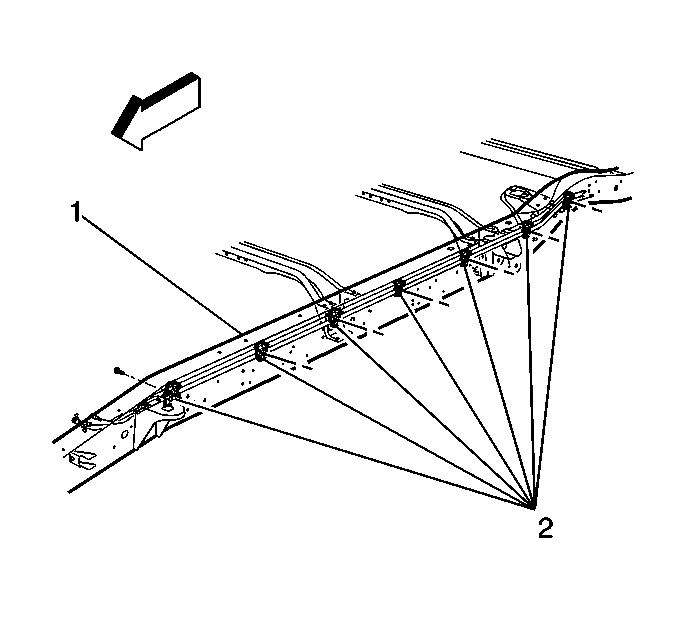
- Install the fuel feed and return pipes and the fuel pipe retaining clips (2) to the frame rail (1).
- Connect the chassis fuel feed and return pipes to the rear fuel feed and return pipes (2).
- Connect the chassis fuel return pipe (4) to the rear fuel return pipe (2).
- Connect the fuel feed pipe (7) to the fuel filter (6).
- Lower the vehicle.
- Refill the fuel tank.
- Tighten the fuel filler cap.
- Connect the negative battery cable.
- Inspect for leaks:
- Install the engine cover. Refer to Engine Cover Replacement in Interior Trim.
Notice: Use the correct fastener in the correct location. Replacement fasteners must be the correct part number for that application. Fasteners requiring replacement or fasteners requiring the use of thread locking compound or sealant are identified in the service procedure. Do not use paints, lubricants, or corrosion inhibitors on fasteners or fastener joint surfaces unless specified. These coatings affect fastener torque and joint clamping force and may damage the fastener. Use the correct tightening sequence and specifications when installing fasteners in order to avoid damage to parts and systems.
Tighten
Tighten the bolts to 12 N·m (106 lb in).
| 9.1. | Turn ON the ignition for 2 seconds. |
| 9.2. | Turn OFF the ignition for 10 seconds. |
| 9.3. | Turn ON the ignition switch. |
| 9.4. | Inspect for fuel leaks. |
