- If reusing the fastener, apply threadlock GM P/N United States 12345382, GM P/N Canada 10953489, or equivalent, to the threads of the fuel meter body bracket bolt.
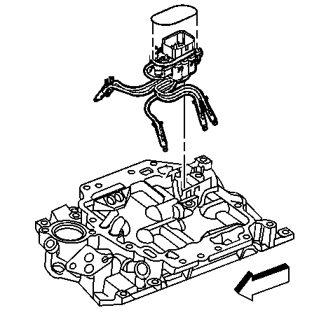
- Install the fuel meter body bracket and bolt.
- Install the fuel meter body into the fuel meter body bracket.
- Install the 6 poppet nozzles into the proper lower intake manifold bores.
- Inspect the poppet nozzles in order to ensure that the poppet nozzles are firmly seated and locked in the lower intake manifold bores.
- Install a NEW fuel meter body seal into the groove of the fuel meter body.
- Install a NEW upper intake manifold to lower intake manifold gasket into the groove of the upper intake manifold.
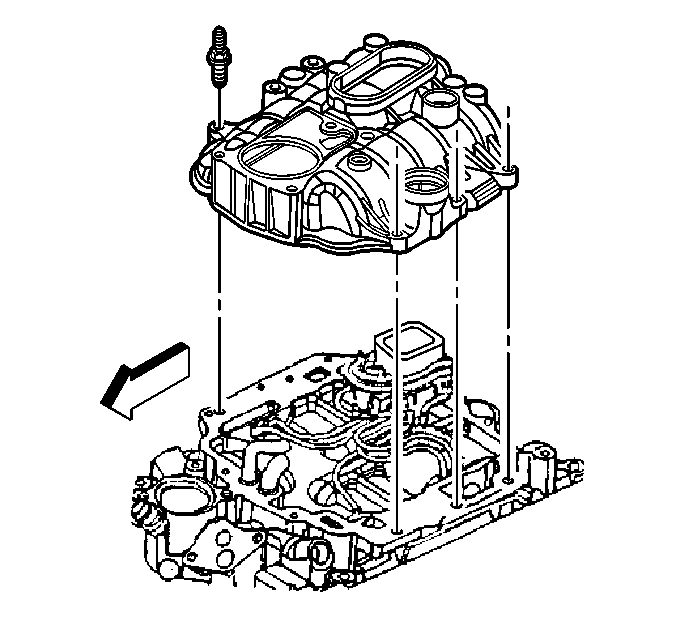
- Install the upper intake manifold onto the lower intake manifold.
- If reusing the fasteners, apply threadlock GM P/N United States 12345382, GM P/N Canada 10953489, or equivalent, to the threads of the upper intake manifold attaching studs.
- Install the upper intake manifold attaching studs.
- Tighten the upper intake manifold attaching studs on the first pass to 5 N·m (44 lb in).
- Tighten the upper intake manifold attaching studs on the final pass to 9 N·m (80 lb in).
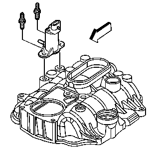
- If reusing the fasteners, apply threadlock GM P/N United States 12345382, GM P/N Canada 10953489, or equivalent, to the threads of the evaporative emission (EVAP) canister purge solenoid valve studs.
- Install the EVAP canister purge solenoid valve and studs.
- Install the engine wiring harness bracket and nut.
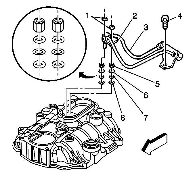
- Install the NEW fuel seals (8), black O-rings, into the fuel meter body.
- Install the NEW spacer rings (7), flat washers, into the fuel meter body.
- Install the NEW fuel seals (6), yellow O-rings, into the fuel meter body.
- Install the NEW fuel seal retainers (5) into the fuel meter body.
- Install the fuel pipe (3) into the fuel meter body.
- Install the fuel pipe retainer bracket (2) onto the fuel pipe.
- Install the fuel pipe retainer bracket nuts (1).
- If reusing the fastener, apply threadlock GM P/N United States 12345382, GM P/N Canada 10953489, or equivalent, to the threads of the fuel pipe bolt.
- Install the fuel pipe bolt (4).
- Tighten the fuel pipe bracket nuts to 3 N·m (27 lb in).
- Tighten the fuel pipe bolt to 6 N·m (53 lb in).
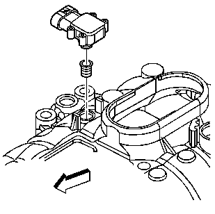
- Install a NEW manifold absolute pressure (MAP) sensor seal onto the MAP sensor.
- Apply a small amount, approximately 1 drop, of clean engine oil to the MAP sensor seal.
- Install the MAP sensor into the upper intake manifold.
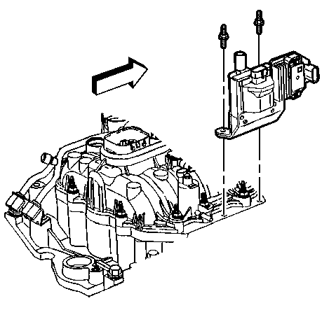
- Install the ignition coil and studs.
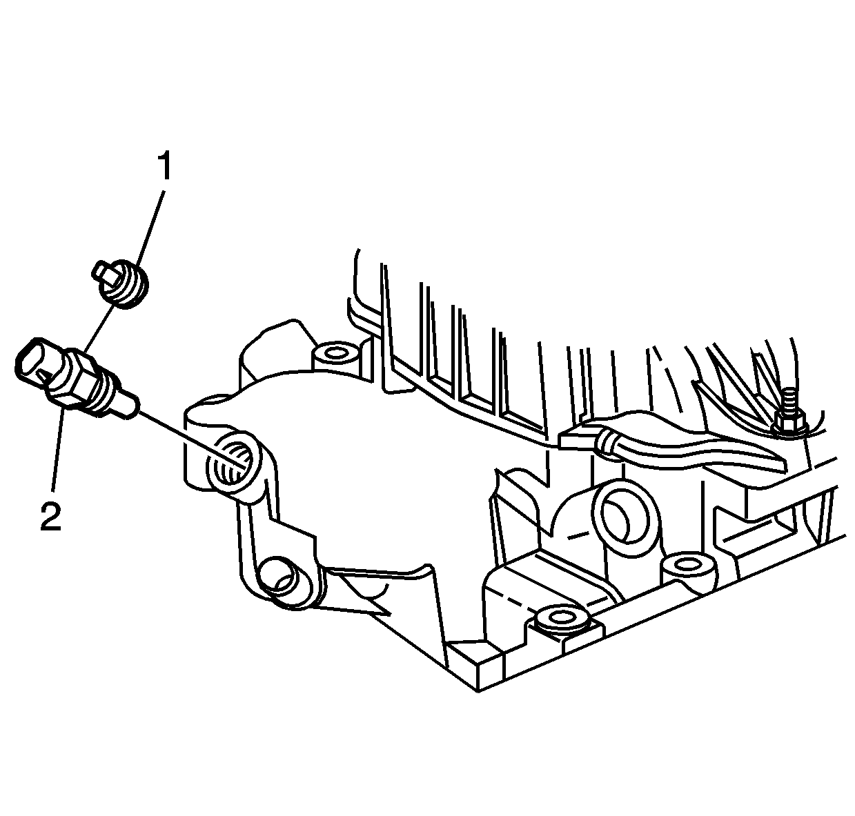
- If reusing the engine coolant temperature (ECT) sensor plug (1) or the ECT sensor (2), if equipped, apply sealant GM P/N United States 12346004, GM P/N Canada 10953480, or equivalent, to the threads of the ECT sensor plug (1) or the ECT sensor (2).
- Install the ECT sensor or plug, if equipped, into the front of the lower intake manifold.
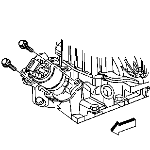
- Install a NEW EGR valve gasket and the EGR valve.
- Install the EGR valve bolts.
- Tighten the EGR valve bolts on the first pass to 7 N·m (62 lb in).
- Tighten the EGR valve bolts on the final pass to 30 N·m (22 lb ft).
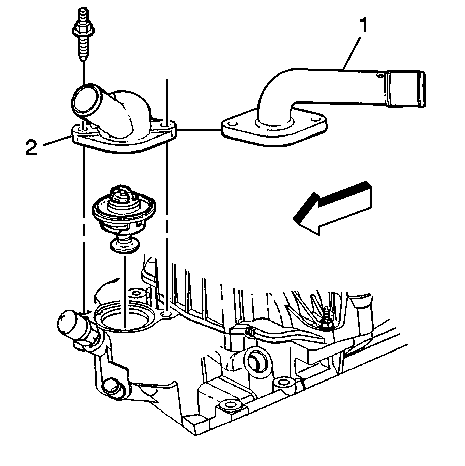
- Install the engine coolant thermostat.
- Install the water outlet (1 or 2).
- Install the water outlet studs.
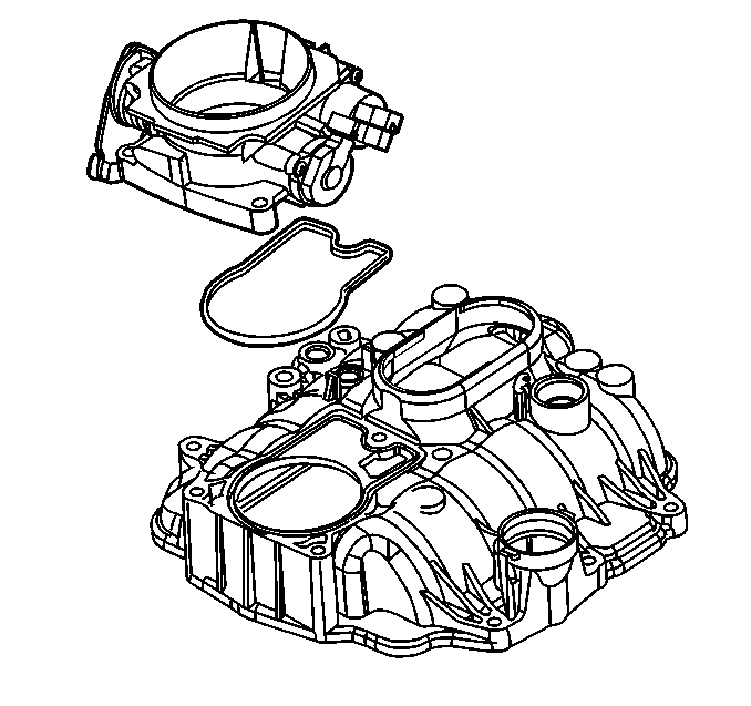
- Install a NEW throttle body gasket into the groove in the upper intake manifold.
- Install the throttle body onto the upper intake manifold.
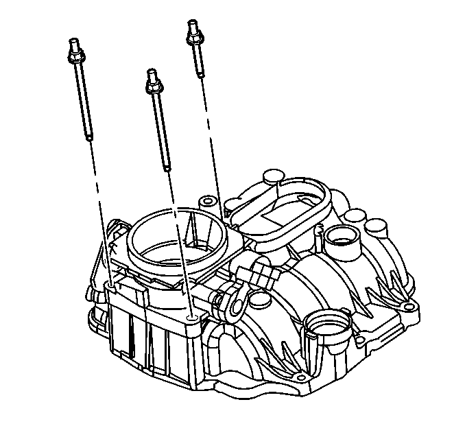
- If reusing the fasteners, apply threadlock GM P/N United States 12345382, GM P/N Canada 10953489, or equivalent, to the threads of the throttle body attaching studs.
- Install the throttle body attaching studs.
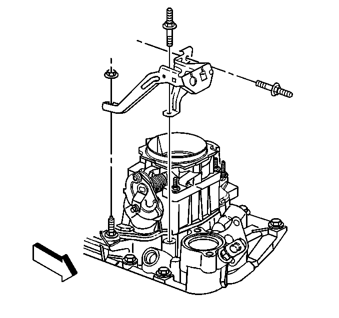
- Install the accelerator control cable bracket, the studs, and the nuts.
- Tighten the accelerator control cable bracket stud to the intake manifold to 6 N·m (53 lb in).
- Tighten the accelerator control cable bracket nuts to 12 N·m (106 lb in).
- Tighten the accelerator control cable bracket stud to the throttle body to 12 N·m (106 lb in).
Notice: Use the correct fastener in the correct location. Replacement fasteners must be the correct part number for that application. Fasteners requiring replacement or fasteners requiring the use of thread locking compound or sealant are identified in the service procedure. Do not use paints, lubricants, or corrosion inhibitors on fasteners or fastener joint surfaces unless specified. These coatings affect fastener torque and joint clamping force and may damage the fastener. Use the correct tightening sequence and specifications when installing fasteners in order to avoid damage to parts and systems.
Tighten
Tighten the fuel meter bracket bolt to 10 N·m (89 lb in).
Tighten
Tighten
Tighten the EVAP canister purge solenoid valve studs to 10 N·m
(89 lb in).
Tighten
Tighten the engine wiring harness bracket nut to 12 N·m
(106 lb in).
Tighten
Tighten
Tighten the ignition coil studs to 12 N·m (106 lb in).
Tighten
Tighten the ECT sensor or plug to 20 N·m (15 lb ft).
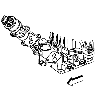
Important: The exhaust gas recirculation (EGR) valve must be installed in the original orientation.
Tighten
Tighten
Tighten the water outlet studs to 25 N·m (18 lb ft).
Tighten
Tighten the throttle body attaching studs to 9 N·m (80 lb in).
Tighten
