GM Service Manual Online
For 1990-2009 cars only

Object Number: 355702  Size: MF

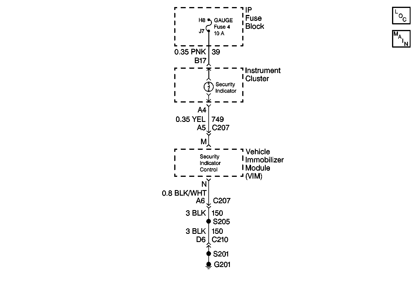
Circuit Description

The VIM controls the operation of the SECURITY indicator lamp by providing ground at terminal M. Lamp control is based upon inputs from the following components:

    • The VCM (Class 2 Data, terminal C and terminal D)
    • The ignition switch (Ignition 1, terminal J, CKT 39)
    • The brake pedal (Stop Lamps, terminal L)
    • The SECURITY indicator (SECURITY Indicator Control, terminal M)
    • The signals received from the transmitter in the key fob

Conditions for Setting the DTC

When the VIM is commanding the lamp to turn off, and the voltage is measured at the VIM terminal M is less than 2 volts, DTC B0687 is set.

Conditions for Clearing the MIL/DTC

  1. A history DTC will clear after 100 consecutive ignition cycles occur without a fault.
  2. Use the Scan Tool in order to clear the history and the current DTCs.

Diagnostic Aids

Most intermittent faults are caused by a faulty electrical connection or the wiring. Damaged VIM's are occasionally at fault. Refer to Intermittent and Poor Connections in Troubleshooting Procedures for a detailed explanation of how to locate and repair intermittent conditions.

Test Description

The number(s) below refer to the step number(s) in the Security System Indicator Circuit Low Table.

  1. This test identifies the malfunction as lamp does not come on (open circuit) or lamp always on (short to ground).

  2. This test inspects for an open power feed fuse to the lamp

  3. This test inspects for a circuit malfunction causing the open fuse.

  4. This test inspects that the Vehicle Immobilizer Module (VIM) is receiving the ignition 1 signal (no open in the power feed wire).

  5. This test inspects for an open indicator lamp bulb.

  6. This test inspects for an open in the SECURITY indicator control circuit.

  7. This test inspects for bad connections that prevent the lamp from lighting.

  8. This test inspects for a short to ground in the SECURITY indicator control circuit.

  9. This test determines if the malfunction is due to a short to ground in the SECURITY indicator control circuit.

Step

Action

Value(s)

Yes

No

1

Was the On-Board Diagnostic (OBD) System Check performed?

--

Go to Step 2

    •  Powertrain On Board Diagnostic (OBD) System Check in Engine Controls - 4.3L
    •  Powertrain On Board Diagnostic (OBD) System Check in Engine Controls - 5.0,5.7L
    •  Powertrain On Board Diagnostic (OBD) System Check in Engine Controls - 6.5L
    •  Malfunction Indicator Lamp Circuit Check in Engine Controls - 7.4L

2

Turn the ignition switch to the RUN position.

Did the SECURITY lamp light?

--

Go to Step 16

Go to Step 3

3

  1. Turn the ignition switch to the OFF position.
  2. Remove the GAUGES fuse (Fuse 4).
  3. Inspect the GAUGES fuse (Fuse 4).

Is the GAUGES fuse (Fuse 4) open?

--

Go to Step 4

Go to Step 7

4

Inspect for a short to ground in CKT 39.

Was a short to ground in CKT 39 found?

--

Go to Step 5

Go to Step 6

5

  1. Repair the short to ground in CKT 39.
  2. Replace the GAUGES fuse (Fuse 4).

Is the repair complete?

--

    •  Powertrain On Board Diagnostic (OBD) System Check in Engine Controls - 4.3L
    •  Powertrain On Board Diagnostic (OBD) System Check in Engine Controls - 5.0,5.7L
    •  Powertrain On Board Diagnostic (OBD) System Check in Engine Controls - 6.5L
    •  Malfunction Indicator Lamp Circuit Check in Engine Controls - 7.4L

--

6

  1. Replace the GAUGES fuse (Fuse 4)
  2. Clear the DTCs.

Is the repair complete?

--

    •  Powertrain On Board Diagnostic (OBD) System Check in Engine Controls - 4.3L
    •  Powertrain On Board Diagnostic (OBD) System Check in Engine Controls - 5.0,5.7L
    •  Powertrain On Board Diagnostic (OBD) System Check in Engine Controls - 6.5L
    •  Malfunction Indicator Lamp Circuit Check in Engine Controls - 7.4L

--

7

  1. Install the GAUGES fuse (Fuse 4).
  2. Ensure that all of the vehicle doors are closed.
  3. Ensure that the following components are off:
  4. • The Dome Lamp switch
    • The Dome Lamp Defeat switch
  5. Use a Power Door Lock switch in order to unlock the doors.
  6. Turn the ignition switch to the RUN position.

Do the Dome And Courtesy lamps come on and then go off when the ignition switch is turned to the RUN position?

--

Go to Step 9

Go to Step 8

8

  1. Turn the ignition switch to the OFF position.
  2. Repair the open in CKT 39.
  3. Clear the DTCs.

Is the repair complete?

--

    •  Powertrain On Board Diagnostic (OBD) System Check in Engine Controls - 4.3L
    •  Powertrain On Board Diagnostic (OBD) System Check in Engine Controls - 5.0,5.7L
    •  Powertrain On Board Diagnostic (OBD) System Check in Engine Controls - 6.5L
    •  Malfunction Indicator Lamp Circuit Check in Engine Controls - 7.4L

--

9

  1. Turn the ignition switch to the OFF position.
  2. Disconnect the Instrument Panel Cluster.
  3. Remove the SECURITY indicator bulb.
  4. Inspect the SECURITY indicator bulb.

Is the SECURITY indicator bulb open?

--

Go to Step 10

Go to Step 11

10

  1. Replace the SECURITY indicator bulb.
  2. Reconnect the Instrument Panel Cluster.
  3. Clear the DTCs.

Is the repair complete?

--

    •  Powertrain On Board Diagnostic (OBD) System Check in Engine Controls - 4.3L
    •  Powertrain On Board Diagnostic (OBD) System Check in Engine Controls - 5.0,5.7L
    •  Powertrain On Board Diagnostic (OBD) System Check in Engine Controls - 6.5L
    •  Malfunction Indicator Lamp Circuit Check in Engine Controls - 7.4L

--

11

  1. Disconnect the Vehicle Immobilizer Module.
  2. Measure the resistance from the VIM harness connector terminal M to the Instrument Panel Cluster terminal A4.

Is the resistance within the specified range?

Less than 5ohms

Go to Step 13

Go to Step 12

12

  1. Repair the open in CKT 749
  2. Reconnect the Instrument Panel Cluster.
  3. Reconnect the VIM.
  4. Clear the DTCs.

Is the repair complete?

--

    •  Powertrain On Board Diagnostic (OBD) System Check in Engine Controls - 4.3L
    •  Powertrain On Board Diagnostic (OBD) System Check in Engine Controls - 5.0,5.7L
    •  Powertrain On Board Diagnostic (OBD) System Check in Engine Controls - 6.5L
    •  Malfunction Indicator Lamp Circuit Check in Engine Controls - 7.4L

--

13

  1. Inspect for a proper connection to the Instrument Panel Cluster at the following terminals:
  2. • Terminal A4
    • Terminal B17
  3. Inspect for a proper connection to the VIM at the terminal M.

Are all of the connections good?

--

Go to Step 14

Go to Step 15

14

  1. Service the Instrument Panel Cluster.
  2. Reconnect the Instrument Panel Cluster.
  3. Reconnect the VIM.
  4. Clear the DTCs.

Is the repair complete?

--

    •  Powertrain On Board Diagnostic (OBD) System Check in Engine Controls - 4.3L
    •  Powertrain On Board Diagnostic (OBD) System Check in Engine Controls - 5.0,5.7L
    •  Powertrain On Board Diagnostic (OBD) System Check in Engine Controls - 6.5L
    •  Malfunction Indicator Lamp Circuit Check in Engine Controls - 7.4L

--

15

  1. Repair or replace the connections if necessary.
  2. Reconnect the Instrument Cluster.
  3. Reconnect the Instrument Panel Cluster.
  4. Reconnect the VIM.
  5. Clear the DTCs.

Is the repair complete?

--

    •  Powertrain On Board Diagnostic (OBD) System Check in Engine Controls - 4.3L
    •  Powertrain On Board Diagnostic (OBD) System Check in Engine Controls - 5.0,5.7L
    •  Powertrain On Board Diagnostic (OBD) System Check in Engine Controls - 6.5L
    •  Malfunction Indicator Lamp Circuit Check in Engine Controls - 7.4L

--

16

  1. Turn the ignition switch to the OFF position.
  2. Disconnect the Instrument Panel Cluster.
  3. Disconnect the VIM.
  4. Measure the resistance on the VIM harness connector from the terminal M to the terminal N (Ground).

Is the resistance at or above the specified value?

OL (infinite)

Go to Step 18

Go to Step 17

17

  1. Repair the short to ground in CKT 749.
  2. Reconnect the Instrument Panel Cluster.
  3. Reconnect the VIM.
  4. Clear the DTCs.

Is the repair complete?

--

    •  Powertrain On Board Diagnostic (OBD) System Check in Engine Controls - 4.3L
    •  Powertrain On Board Diagnostic (OBD) System Check in Engine Controls - 5.0,5.7L
    •  Powertrain On Board Diagnostic (OBD) System Check in Engine Controls - 6.5L
    •  Malfunction Indicator Lamp Circuit Check in Engine Controls - 7.4L

--

18

  1. Reconnect the Instrument Panel Cluster.
  2. Turn the ignition switch to the RUN position.

Does the SECURITY lamp light?

--

Go to Step 19

Go to Step 20

19

  1. Turn the ignition switch to the OFF position.
  2. Service the Instrument Panel Cluster.
  3. Reconnect the Instrument Panel Cluster.
  4. Reconnect the VIM.
  5. Clear the DTCs.

Is the repair complete?

--

    •  Powertrain On Board Diagnostic (OBD) System Check in Engine Controls - 4.3L
    •  Powertrain On Board Diagnostic (OBD) System Check in Engine Controls - 5.0,5.7L
    •  Powertrain On Board Diagnostic (OBD) System Check in Engine Controls - 6.5L
    •  Malfunction Indicator Lamp Circuit Check in Engine Controls - 7.4L

--

20

  1. Turn the ignition switch to the OFF position.
  2. Replace the VIM.
  3. Reconnect the Instrument Panel Cluster.

Is the repair complete?

--

    •  Powertrain On Board Diagnostic (OBD) System Check in Engine Controls - 4.3L
    •  Powertrain On Board Diagnostic (OBD) System Check in Engine Controls - 5.0,5.7L
    •  Powertrain On Board Diagnostic (OBD) System Check in Engine Controls - 6.5L
    •  Malfunction Indicator Lamp Circuit Check in Engine Controls - 7.4L

--