DTC B0688 Security System Indicator Circuit High Domestic

Circuit Description
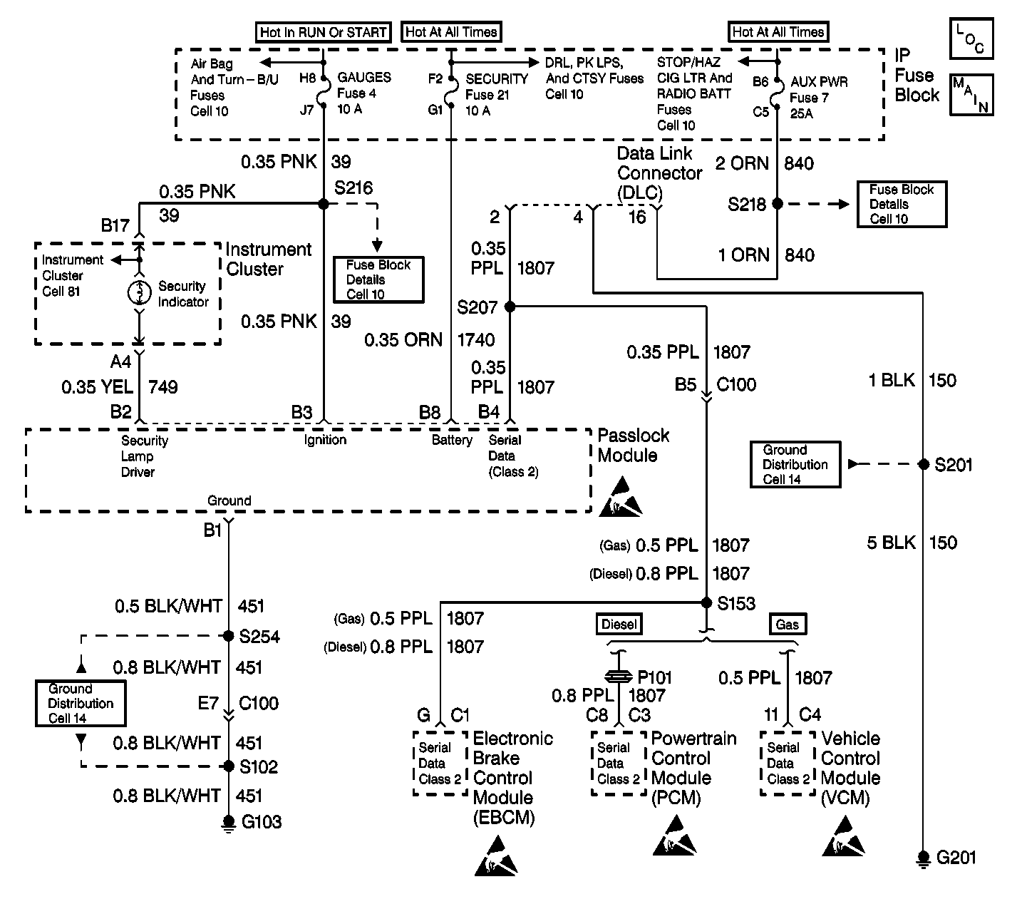
The security indicator is a hardwired lamp that receives power form the gauges fuse 4 through CKT 39.
Conditions for Setting the DTC
| • | The ignition switch is ON. |
| • | The Passlock module is unable to provide a complete path to ground for the security indicator due to a wiring fault or a defective Passlock module. |
Action Taken When the DTC Sets
| • | The ignition switch is ON. |
| • | The security indicator is commanded ON. |
| • | The Passlock module connector terminal B2 voltage is greater than 2.9 volts. |
| • | The security indicator may be on when the ignition switch is OFF if CKT 749 is shorted to battery power. |
Conditions for Clearing the DTC
| • | The DTC will clear after an ignition cycle has occurred without the fault. |
| • | The Passlock module history codes will be cleared after 100 ignition cycles with no current codes active. |
| • | Using a scan tool. |
Diagnostic Aids
| • | Perform a visual inspection of the wiring and the connectors. |
| • | Inspect the Passlock sensor harness for an intermittent or a short to battery. Refer to Intermittents and Poor Connections . |
Test Description
The numbers below refer to the numbers on the diagnostic table:
-
This step isolates the problem between the harness and the Passlock module.
-
This step isolates the problem between the instrument cluster and the harness
Step | Action | Value(s) | Yes | No |
|---|---|---|---|---|
1 | Did you perform the VTD Diagnostic System Check? | -- | Go to Step 2 | |
Is the voltage within the specified range? | 9-16 volts | Go to Step 3 | Go to 5 | |
Is the voltage within the specified range? | 9-16 volts | Go to Step 4 | Go to Step 6 | |
4 | Repair the short to battery in CKT 749. Is the repair complete? | -- | -- | |
5 | Replace the Passlock module. Refer to Theft Deterrent Module Replacement . Is the repair complete? | -- | Go to Step 7 | -- |
6 | Replace the instrument cluster. Refer to Instrument Cluster Replacement in Instrument Panel, Gauges and Console. Is the repair complete? | -- | -- | |
7 |
Is the repair complete? | -- | -- |
DTC B0688 Security System Indicator Circuit High Export

Circuit Description
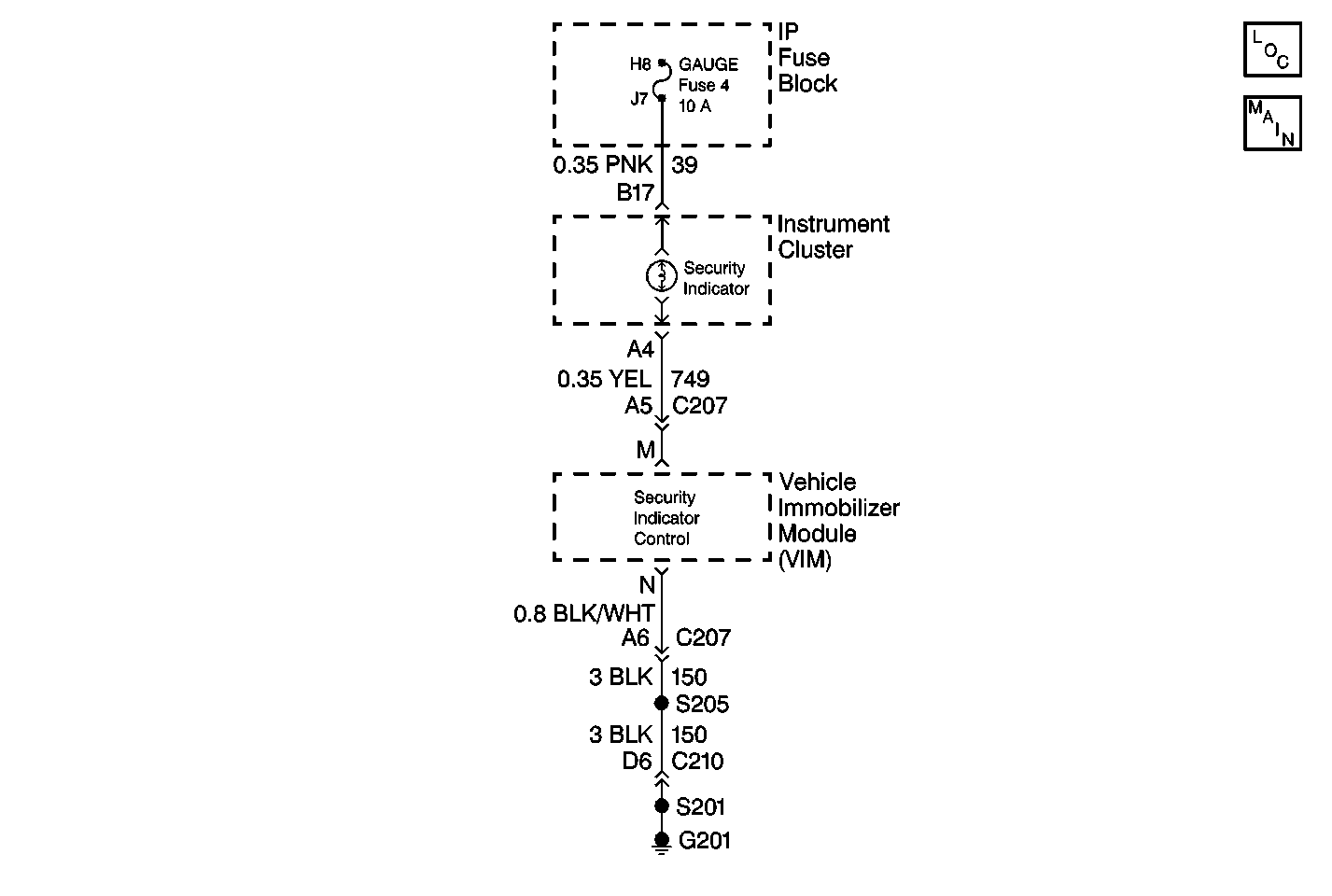
The Vehicle Immobilizer Module (VIM) controls the operation of the SECURITY indicator lamp by providing ground at the VIM terminal M. Lamp control is based upon signals received from the transmitter in the key fob and inputs from the following components:
| • | the VCM (Class 2 Data, terminal C and terminal D) |
| • | the ignition switch (Ignition 1, terminal J) |
| • | the brake pedal (Stop Lamps, terminal L) |
| • | the SECURITY indicator (SECURITY Indicator Control, terminal M) |
Conditions for Setting the DTC
When the VIM is commanding the lamp on and the voltage measured at VIM terminal M is greater than 7 volts, DTC B0688 is set.
Conditions for Clearing the MIL/DTC
| • | A history DTC will clear after 100 consecutive ignition cycles have occurred without a fault. |
| • | History and current DTCs can be cleared by using the Tech 2 scan tool. |
Intermittent and Poor Connections
Most intermittent faults are caused by a faulty electrical connection or wiring, although a damaged VIM module can occasionally be at fault. Refer to Intermittents and Poor Connections Diagnosis in Wiring Systems for a detailed explanation of how to locate and repair intermittent conditions.
Test Description
The number(s) below refer to the step number(s) on the diagnostic table.
-
This test inspects for a short to voltage in the SECURITY indicator control circuit.
-
This test inspects for a shorted indicator lamp.
-
This test determines whether the malfunction is due to a short to voltage in the Instrument Panel Cluster circuitry or a malfunctioning Vehicle Immobilizer Module (VIM).
Step | Action | Value(s) | Yes | No | ||||
|---|---|---|---|---|---|---|---|---|
1 | Was the On-Board Diagnostic (OBD) System Check performed? | Less than 1V | Go to Step 2 |
| ||||
2 |
Is the voltage less than 1V? | -- | Go to Step 4 | Go to Step 3 | ||||
3 |
Is the repair complete? | -- |
| -- | ||||
4 |
Is there a short in the SECURITY indicator bulb? | -- | Go to Step 5 | Go to Step 6 | ||||
5 |
Is the repair complete? | -- |
| -- | ||||
6 |
Is the voltage less than 1V? | Less than 1V | Go to Step 7 | Go to Step 8 | ||||
7 |
Is the repair complete? | -- |
| -- | ||||
8 |
Is the repair complete? | -- |
| -- |
