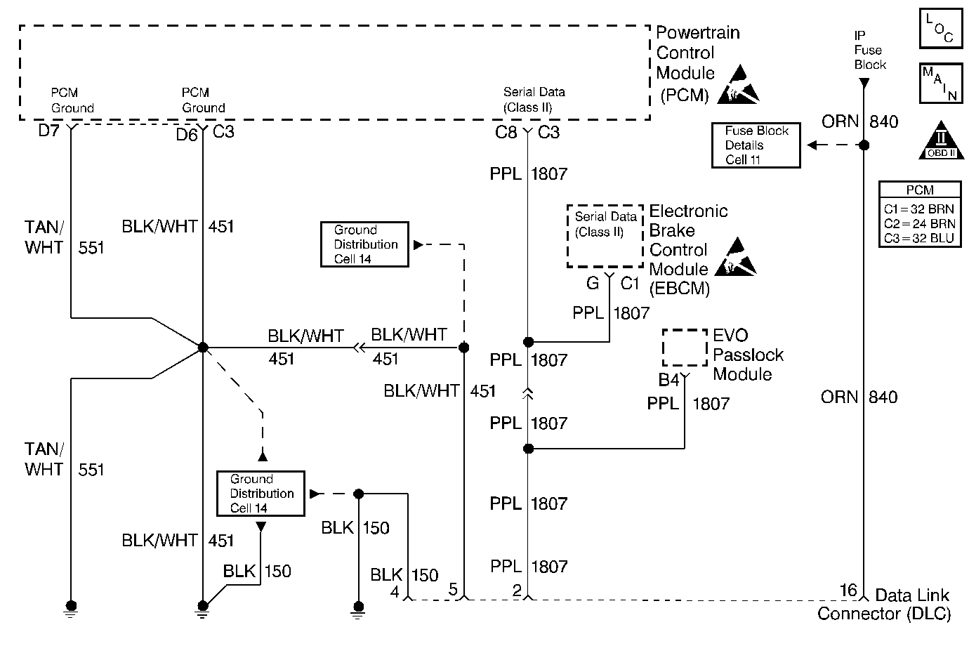
Circuit Description
The PCM monitors the serial data (class II) circuit for communications from the Passlock/EVO controller. If no message is being sent form thePasslock/EVO controller this DTC will set.
Conditions for Setting the DTC
No communications on serial data (class II) circuit from Passlock/EVO controller.
Action Taken When the DTC Sets
This DTC will not illuminate the MIL.
Conditions for Clearing the MIL/DTC
| • | A History DTC will clear after 40 consecutive warm-up if no failures are reported by this or any other emissions related diagnostic. |
| • | PCM battery voltage is interrupted. |
| • | Use of a scan tool. |
Diagnostic Aids
This DTC will only diagnosis an open or intermittent connection from the Passlock/EVO controller to the splice.
Test Description
The number(s) below refer to the step number(s) on the Diagnostic Table.
-
In this step, the scan tool is checking for communication between the PCM and the Passlock/EVO controller.
-
This step checks the serial data circuit from the Passlock/EVO to the splice for an open or proper connection.
Step | Action | Value(s) | Yes | No | ||||
|---|---|---|---|---|---|---|---|---|
1 |
Important:: Before clearing DTCs, use the Scan Tool Capture Info to record Freeze Frame and Failure Records for reference, as data will be lost when Clear Info function is used. Was the Powertrain On-Board Diagnostic (OBD) System Check performed? | -- | ||||||
Does the scan tool display Passlock/EVO controller Active? | -- | |||||||
3 | The DTC is intermittent. If no additional DTCs are stored, refer to diagnostic aids. If any additional DTCs were stored, refer to the applicable DTC table(s) first. Are any additional DTCs stored? | -- | Go to the Applicable DTC Table | -- | ||||
Check the Serial Data (Class II) circuit from the Passlock/EVO controller to the splice for the following conditions and repair if necessary:
Was a repair performed? | -- | Go to Passlock/EVO Controller Diagnosis | ||||||
5 |
Does the scan tool indicate that this diagnostic passed? | -- | ||||||
6 | Using the Scan Tool, select Capture Info, Review Info. Are any DTCs displayed that have not been diagnosed? | -- | Go to the Applicable DTC Table | System OK |
