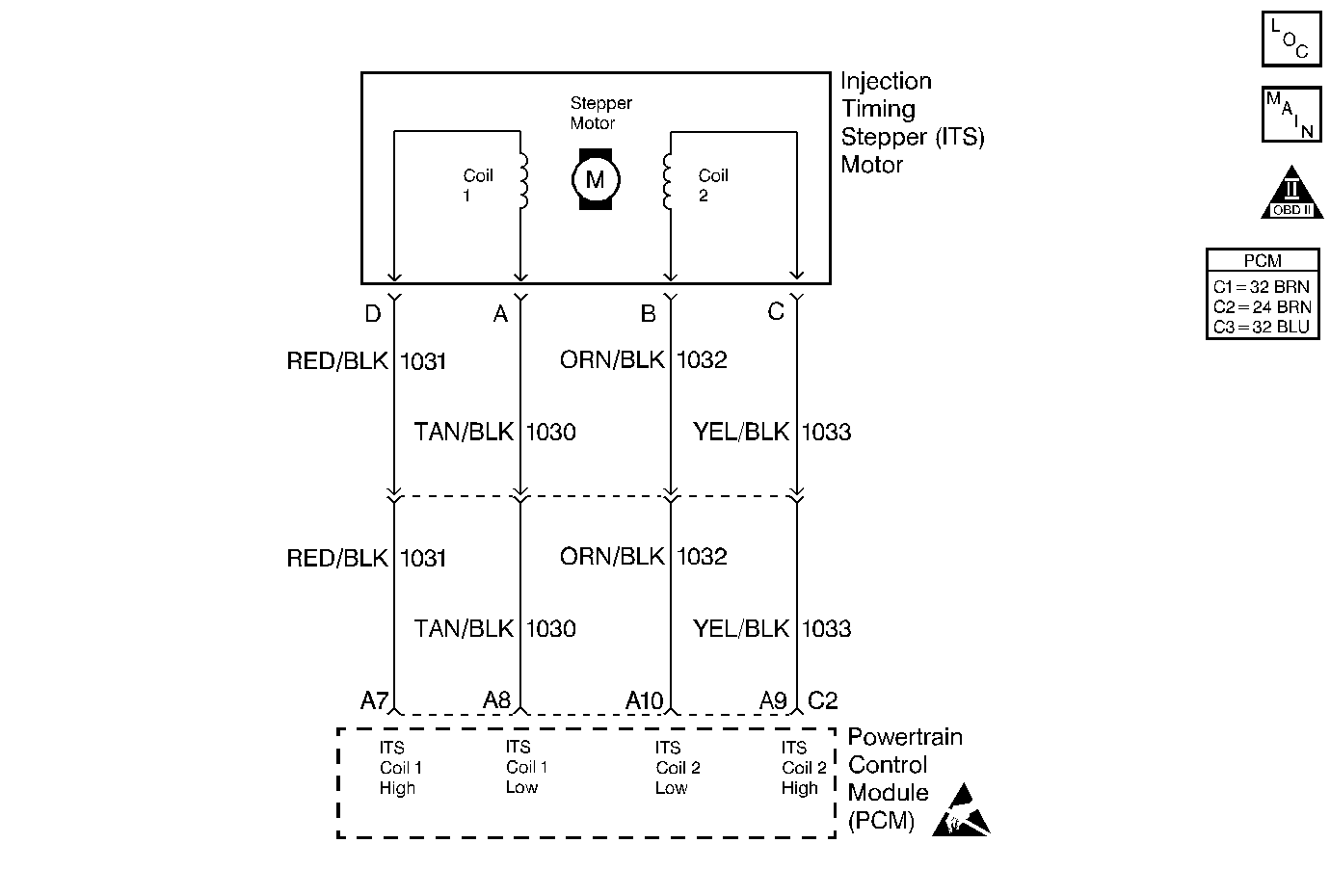
Circuit Description
The timing of the combustion event is accomplished by controlling the beginning of injection measured in degrees of crankshaft roation beforeTop Dead Center. This test compares the desired timing to the measured timing when certain conditions have been met. In order to retard the injection timing, the PCM extends the Stepper motor. To advance the injection timing, the PCM retracts the Stepper motor.
Conditions for Setting the DTC
| • | The engine speed has not changed more than 56 RPM for 20.8 seconds. |
| • | A 5 degree difference between the Act. Inj. Time and the Des. Inj. Time |
Action Taken When the DTC Sets
| • | The PCM illuminates the Malfunction Indicator Lamp (MIL) on the second consecutive drive trip the diagnostic runs and fails. |
| • | The PCM records the operating conditions at the time the diagnostic fails. The first time the diagnostic fails, the Failure Records store this information. If the diagnostic reports a failure on the second consecutive drive trip, the Freeze Frame records the operating conditions at the time of failure and updates the Failure Records. |
Conditions for Clearing the MIL/DTC
| • | The PCM will turn the MIL off after three consecutive trips without a fault condition. |
| • | A History DTC will clear after forty consecutive warm-up cycles during which the diagnostic does not fail (coolant temperature has risen 22°C (40°F) from start up coolant temperature and engine coolant temperature exceeds 71°C (160°F) that same ignition cycle. |
| • | Use of a Scan Tool will clear the DTC codes. |
Diagnostic Aids
An intermittent may be caused by the following:
| • | Poor connections |
| • | A rubbed through wire insulation |
| • | A broken wire inside the insulation |
A hard start and a possible poor performance condition might exist. DTC P0216 will possibly set if the injection timing is not set correctly. Refer to Injection Timing Adjustment for the correct procedure.
Opens or grounds in any of the control circuits may result in full advance and very noisy operation. Check the Snapshot Data to confirm the diagnosis. If the error is less than the Desired Timing, the condition is not caused by a circuit problem. If the error is greater than the Desired Timing, check all of the circuits related to the I.T.S.
Test Description
The number(s) below refer to the step number(s) on the Diagnostic Table.
-
This step determines if DTC P0216 is a hard failure or an intermittent.
-
This step checks for an open or a short in the injection timing coil circuit 1.
-
This step checks for an open or short in the injection timing coil circuit 2.
-
The important thing in this step is that the PCM is sending a varying voltage (voltage may vary between 1 and 12 (usually you will see voltage vary between 5 and 6 when engine is idling)), this will indicate that the PCM is OK and that there is a problem with the injection timing Stepper motor. If there is a steady voltage present on any circuit, this will indicate a problem with the PCM or a circuit shorted to voltage.
Step | Action | Value(s) | Yes | No | ||||||
|---|---|---|---|---|---|---|---|---|---|---|
1 |
Important: Before clearing any DTCs, use the Scan Tool Capture Info to save freeze frame and failure records for reference, as the Scan Tool loses data when using the Clear Info function. Was the Powertrain On-Board Diagnostic (OBD) System Check performed? | -- | ||||||||
Does the Scan Tool display a difference greater than or equal to the specified value between the Actual Inj. Time and the Desired Inj. Time at the idle or at 2700 RPMs? | 5° | |||||||||
3 | The DTC is intermittent. If no additional DTCs are stored, refer to Diagnostic Aids. If any additional DTCs were stored, refer to those table(s) first. Are there any additional DTCs stored? | -- | Go to the applicable DTC Table | Go to Diagnostic Aids
| ||||||
Is the resistance between the specified value? | 10-60 Ohms | |||||||||
Measure the resistance between coil 2 low and coil 2 high at the PCM harness. Is the resistance between the specified value? | 10-60 Ohms | |||||||||
Does the voltage vary on all of the circuits? | -- | |||||||||
7 |
Is the resistance between the specified value? | 950 -1050 Ohms | ||||||||
8 |
Was a repair performed? | -- | ||||||||
9 |
Was a repair performed? | -- | ||||||||
10 |
Was a repair performed? | -- | ||||||||
11 | Check for a poor electrical connection at the injection timing Stepper motor. Did any terminals require a replacement? | -- | ||||||||
12 | Check the circuit for a short to ground or a poor connection at the PCM. Was a repair performed? | -- | ||||||||
13 |
Was a repair performed? | -- | ||||||||
14 | Replace the crankshaft position sensor. Refer to Crankshaft Position Sensor Replacement . Is the action complete? | -- | -- | |||||||
15 | Replace the fuel injection pump. Refer to Fuel Injection Pump Replacement . Important: If the injection pump is malfunctioning, the new injection pump must be timed. Refer to Injection Timing Adjustment . Is the action complete? | -- | -- | |||||||
16 | Replace the PCM. Important: The new PCM must be programmed. Refer to Powertrain Control Module Replacement/Programming . Is the action complete? | -- | -- | |||||||
17 |
Does the Scan Tool indicate the diagnostic Passed? | -- | ||||||||
18 | Does the Scan Tool display any additional undiagnosed DTCs? | -- | Go to the Applicable DTC Table | System OK |
