For 1990-2009 cars only
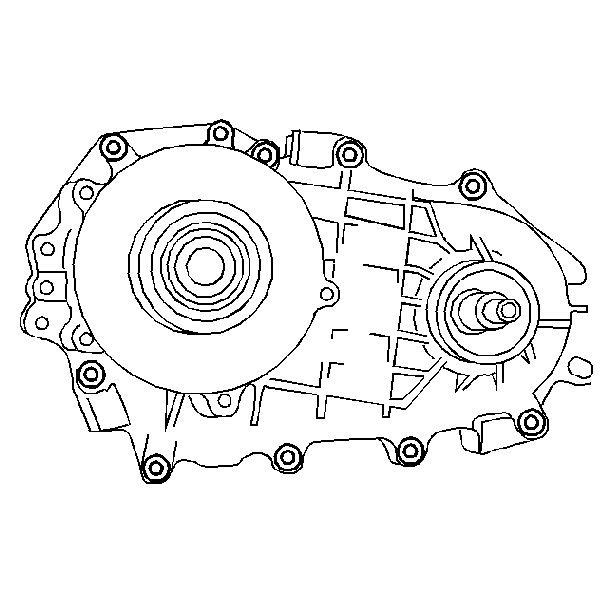
Transfer Case Disassemble Borg-Warner 4472
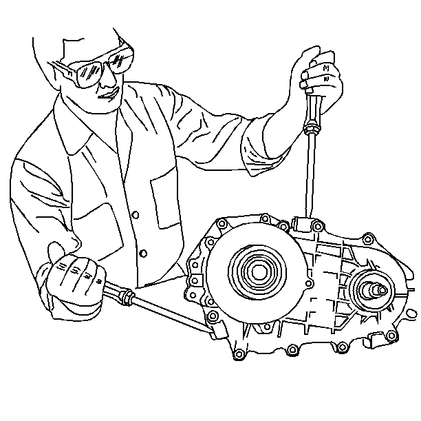
Disassembly Procedure
Tools Required
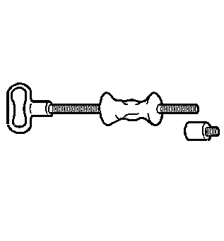
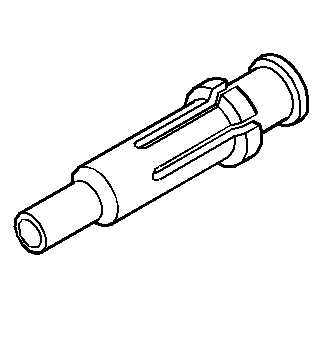
| • | J 22912-O1 Bearing Remover |
| • | J 23907 Puller |
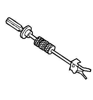
| • | J 2619-01 Slide Hammer |
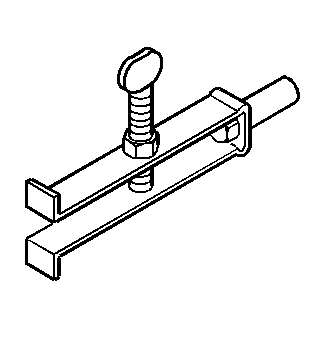
| • | J 29369 Output Shaft Bearing Remover |
| • | J 38427 Output Shaft Needle Bearing Remover |
- Use solvent and a stiff brush in order to clean the transfer case.
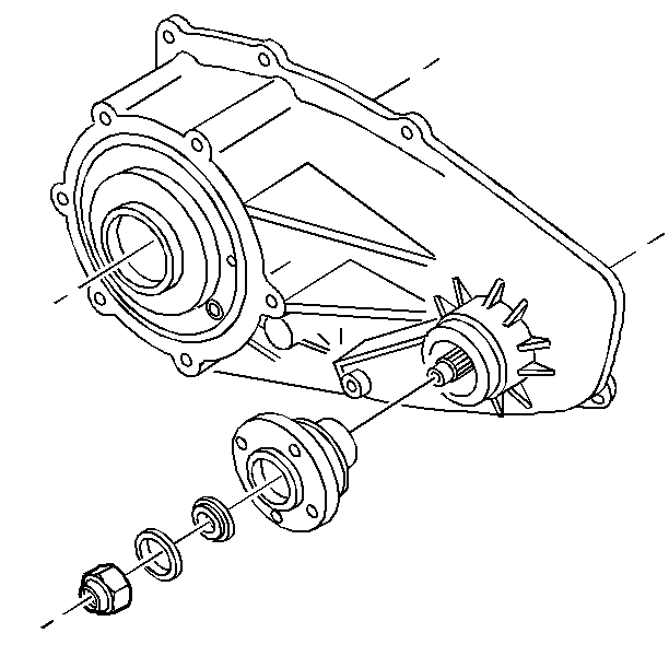
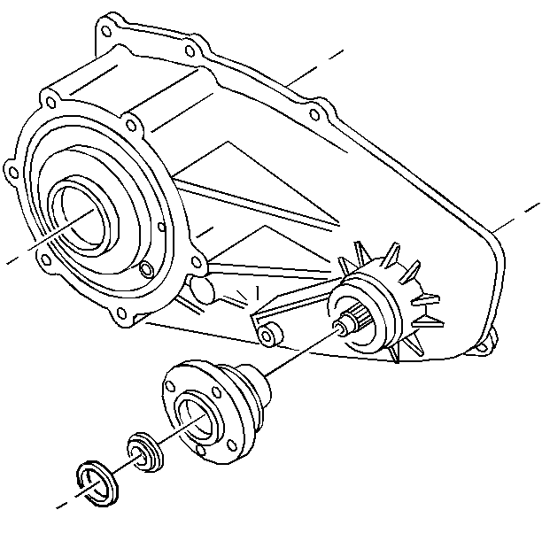
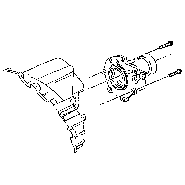
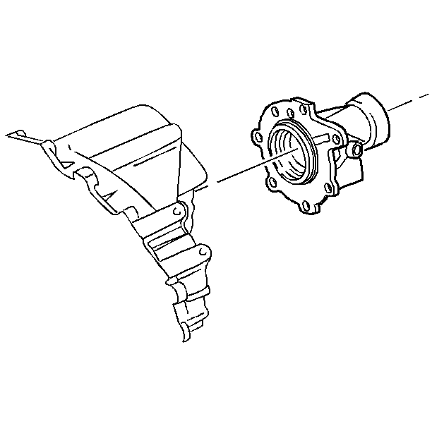
- Remove the front output flange nut.
- Remove the washer.
- Remove the rubber sealing washer.
- Remove the output flange.
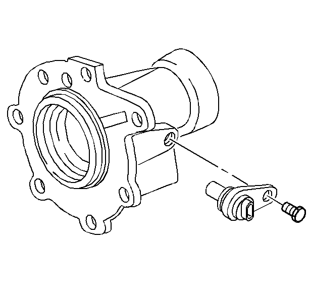
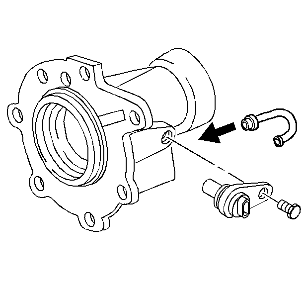
- Remove the vehicle speed sensor bolt.
- Remove the vehicle speed sensor.
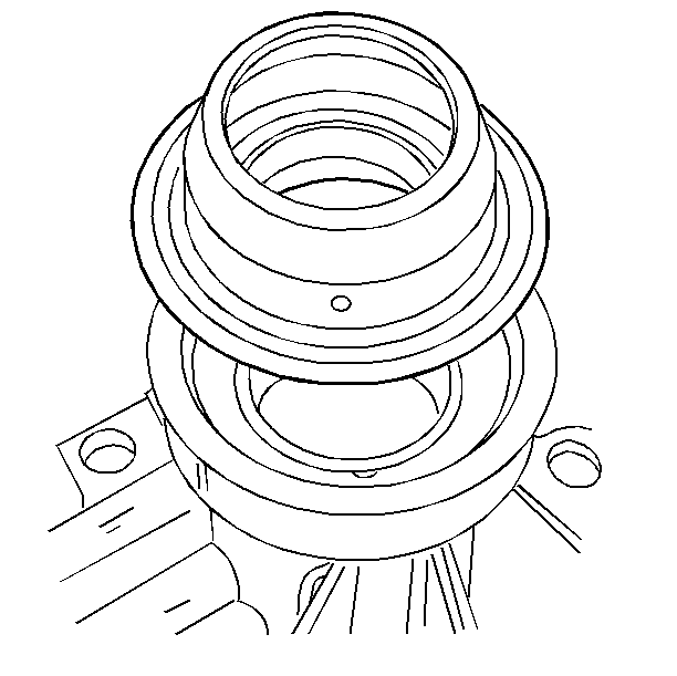
- Remove the front cover to rear case bolts.
- Use screwdrivers in order to remove the front cover. Pry only on the tabs.
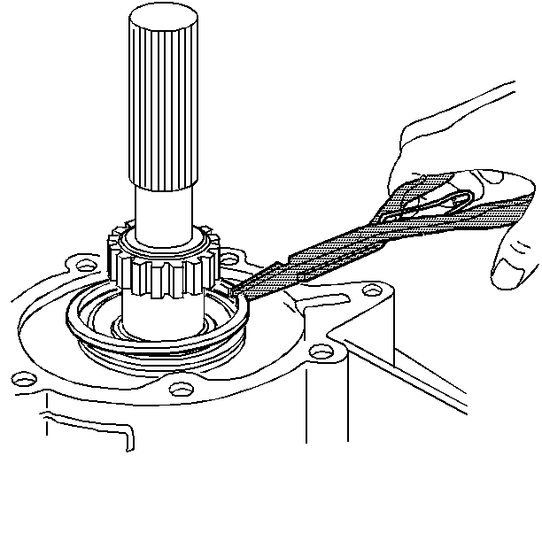
- Remove the front output shaft spacer.
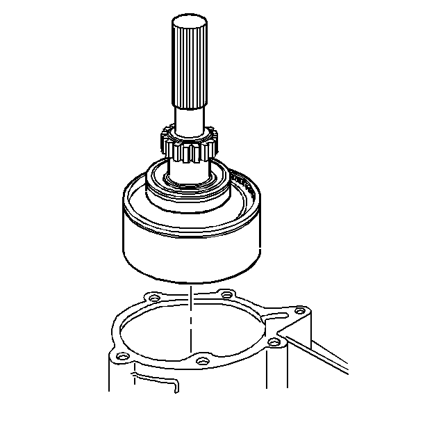
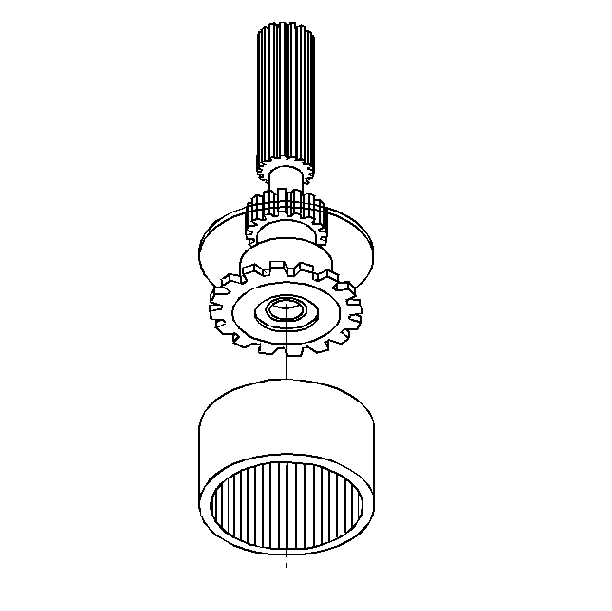
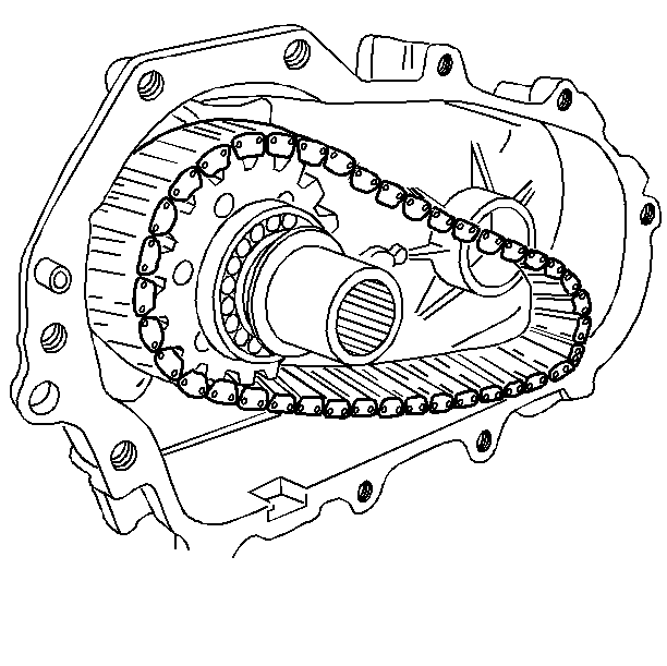
- Remove the front output shaft and drive sprocket.
- Remove the drive chain.
- Remove the magnet.
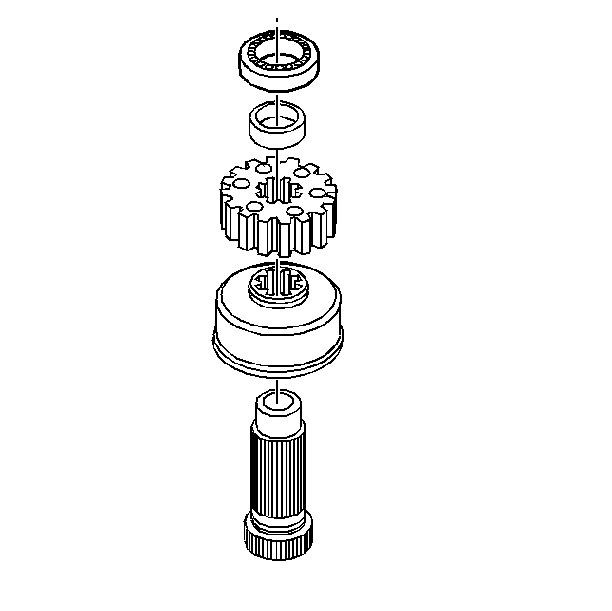
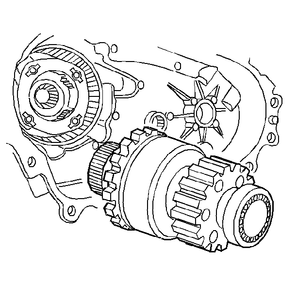
- Remove the input shaft.
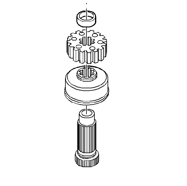
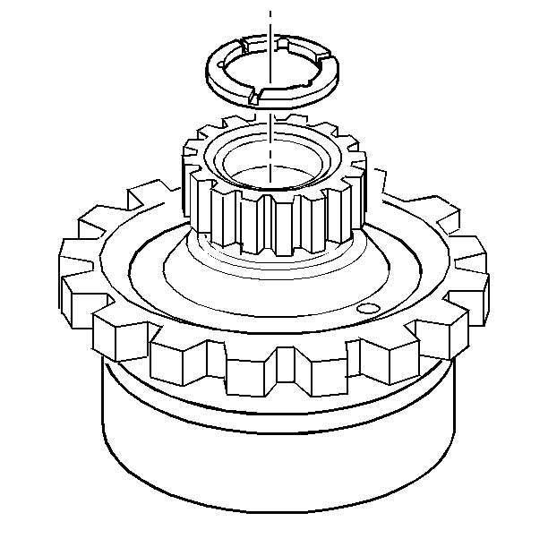
- Remove the sun gear shaft assembly.
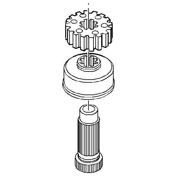
- Remove the thrust washer from the sun gear.
- Remove the planet carrier assembly. The planet carrier assembly includes the thrust washer.
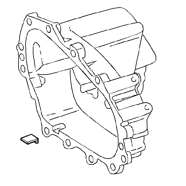
- Remove the seven extension housing bolts.
- Remove the breather assembly.
- Remove the extension housing.
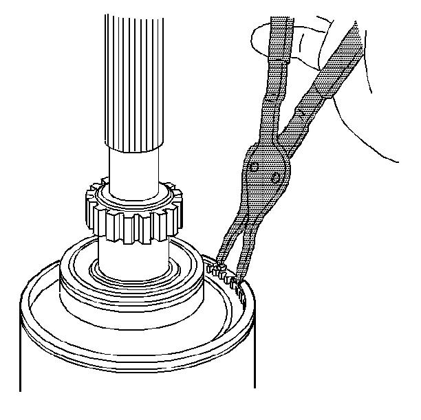
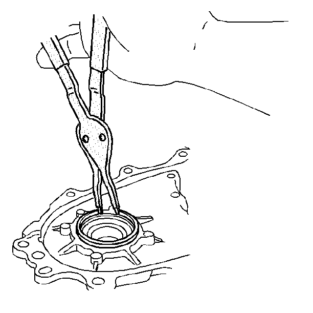
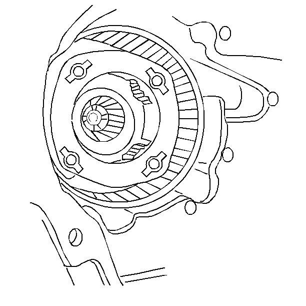
- Remove the snap ring from the output bearing.
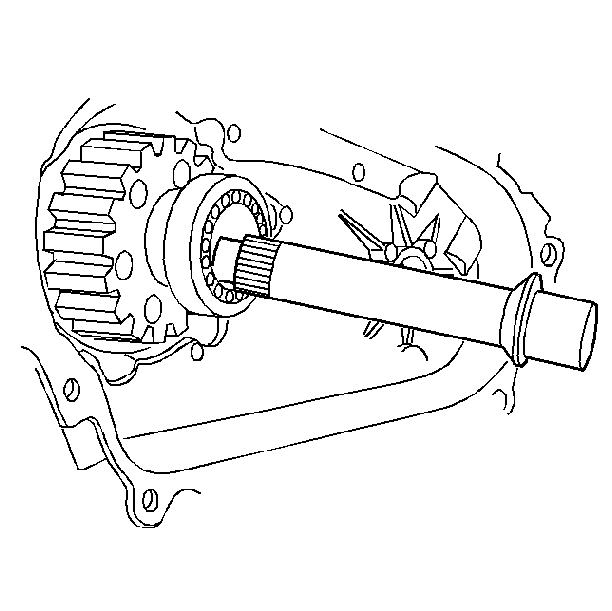
- Remove the input shaft bearing, the output shaft, and the ring gear as one assembly.
- Remove the snap ring.
- Remove the output shaft assembly.
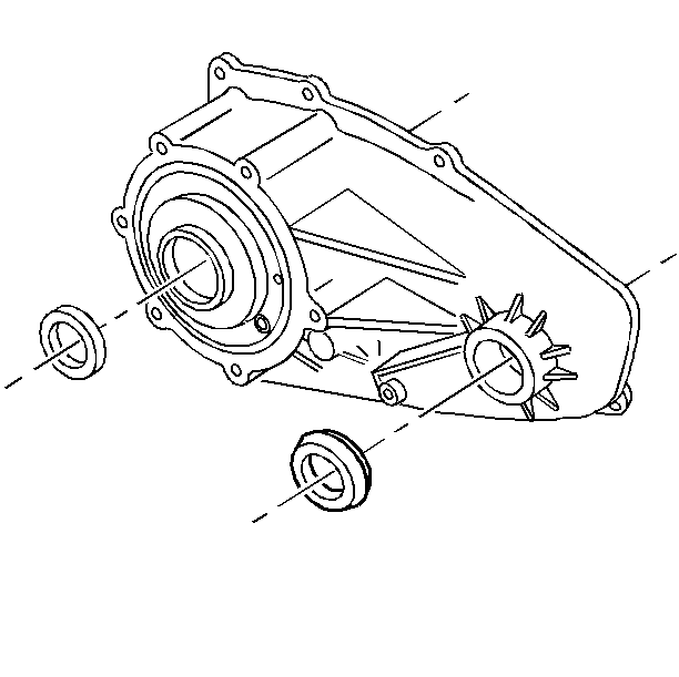
- Remove the front output shaft oil seal.
- Remove the front input shaft oil seal.
- Remove the snap ring.
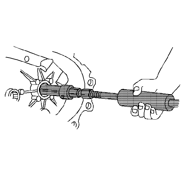
- Use the J 2619-01 and the J 29369 in order to remove the front output shaft bearing.
- Remove the rear output shaft oil seal.
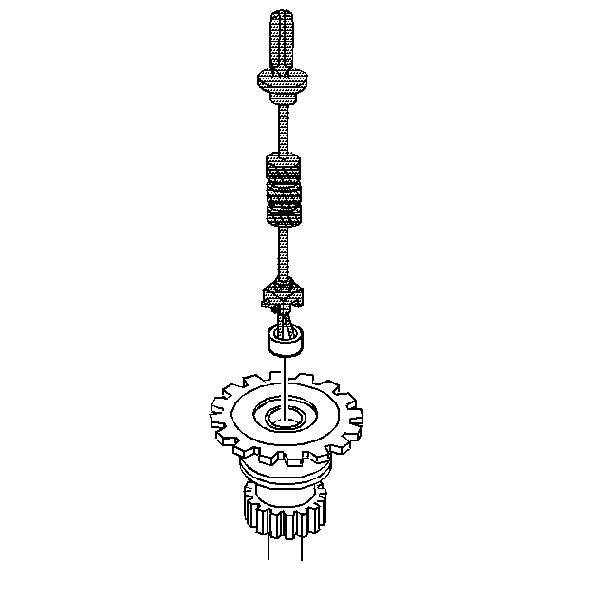
- Use the J 22912-O1 in order to remove the sun gear shaft bearing.
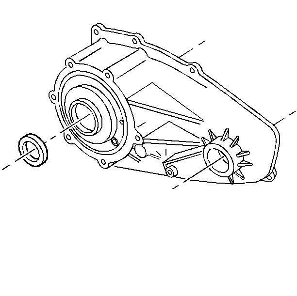
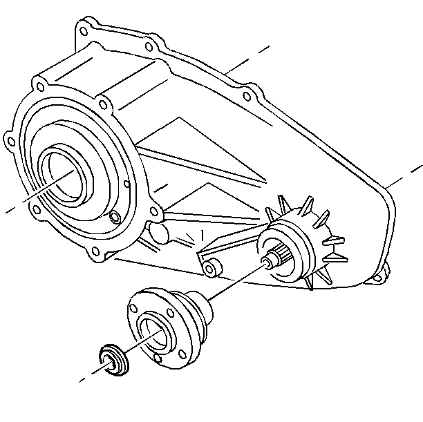
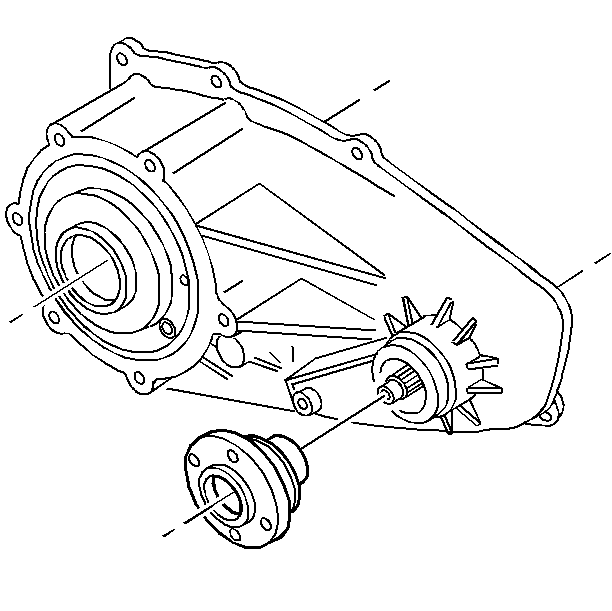
- Remove the drive sprocket spacer.
- Remove the drive sprocket.
- Remove the viscous clutch.
- Use the J 23907 in order to remove the input shaft pilot bushing.
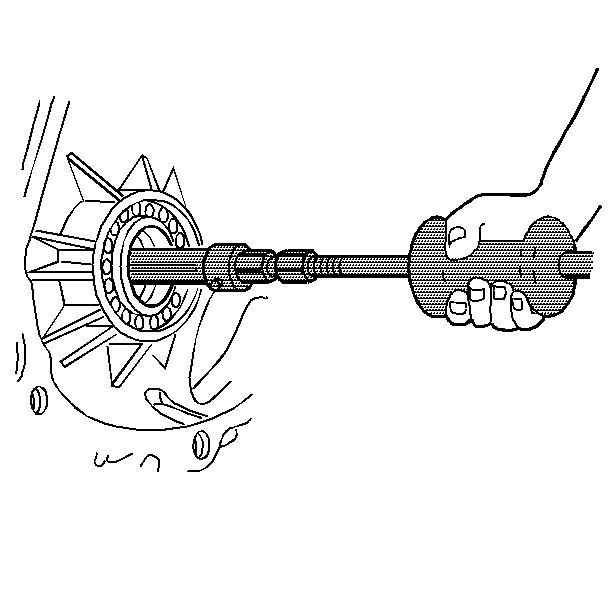
- Use the J 23907 and J 38427 in order to remove the front output shaft rear bearing.
Important: Do not damage the sealing surfaces when prying apart the transfer case.
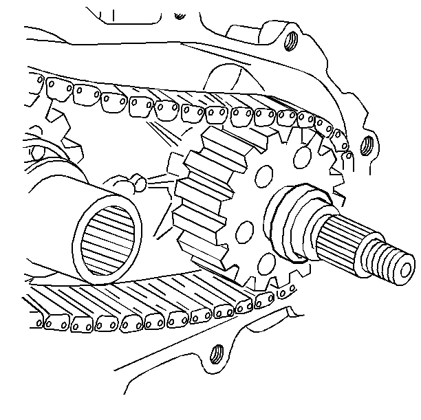
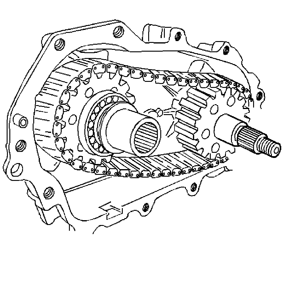
Important: Note the orientation of the letter "E" on the driven sprocket. Note the orientation of the master link for assembly.
| 20.1. | Rotate the transfer case half way. |
| 20.2. | Support the output shaft assembly from the inside. |