Audio System Diagnostic Overview
- Verify the customer complaint.
- Follow the radio service procedures.
- If technical assistance is required, have all the pertinent information
available before you place the call.
Identifying Concerns
| • | Inspect for technical service bulletins. Inspect the dealer communication
system for any applicable preliminary information (P/I) for customer concerns. |
| • | Inspect for stored diagnostic trouble codes. |
| • | For reception concerns, determine if the station is obtainable
in the customer's listening area. |
| • | In order to test for audio reception/noise, position the vehicle
outside of the building with the hood down. |
| • | Duplicate the customer's complaint before you diagnose the system.
Have the customer demonstrate the condition. Test drive the vehicle with the
customer and then test drive another similar model vehicle
(with a similar audio system) in order to make a comparison
of the 2 vehicles. This helps determine if the condition
is abnormal. |
| • | Identify the components and the features of the components before
you diagnose the customer's complaint. |
| • | Determine if any aftermarket equipment is installed on the vehicle.
Disconnect the aftermarket equipment and determine if the customer's complaint
still exists. Follow GM guidelines for installation of aftermarket
components. |
| • | Perform the following steps in order to identify a noisy component: |
| 1. | Identify the ignition key switch position in which the noise appears,
such as accessory, key ON engine not running, and key ON engine running. |
| 3. | Remove the fuses one at a time until the complaint condition has
been eliminated. |
| 4. | Mark the complaint fuse(s). Reinstall all of the fuses. |
| 5. | Disconnect the components powered by the complaint fuse(s) one
at a time until you eliminate the complaint condition. This will identify
the noisy component. |
| 6. | Inspect the ground integrity of the complaint causing component. |
| • | An interference condition is not necessarily an audible noise. |
| • | Most noises are on weak stations near the low end of the band.
These noises are a normal condition. |
| • | Ignition noise on FM possibly indicates a faulty ignition system. |
| • | Malfunctioning and marginal components, relays, and solenoids
may induce noise and/or poor reception. |
Corrective Action
| • | Use the proper tools for diagnostics and repairs. |
| • | Use the following available noise suppression devices: |
| - | 220 mF (50 V) capacitor GM P/N 1227895 |
| - | 0.47 mF capacitor GM P/N 1227894 |
| - | Fuse block capacitor GM P/N 469328 |
| - | Feed through capacitor GM P/N 477371 |
| - | Filter package GM P/N 1224205 |
| - | Turn signal suppression GM P/N 3861565 |
| - | Fuel pump suppressor GM P/N 25027405 |
| - | 21 in braided ground strap GM P/N 8910791 |
| - | 19 in braided ground strap GM P/N 6286800 |
| - | 10.5 in braided ground strap GM P/N 6287160 |
| - | 8.5 in braided ground strap P/N 12091511 |
| • | Utilize the test tape/CD diagnostic kit GM P/N J 39916-A
Speaker Noise - General
in order
to optimize proper audio diagnostics. |
| • | If the condition requires service of the radio at a service center,
describe the symptoms on the warranty form accurately. Along with the warranty
form, send a copy of the service writer check list with
the unit. |
| • | Do not leave a CD or a tape in the car. Extreme heat may cause
permanent damage. |
| • | Cassette tapes may be damaged if not stored in the case. The vibration
in the vehicle may cause the tape to unwind inside the cartridge. |
| • | Inspect all of the connectors and the wiring to the speakers before
you remove the speakers. Examine the connectors for bent or loose pins. Refer
to Troubleshooting Procedures. |
Service Precautions
| • | Inspect the antenna coax connectors for corrosion or bad connections/crimps.
Route coax separately from the other wires. Shield the antenna coax interconnections
with aluminum or nickel tape. |
| • | Verify all vehicle grounds, not just the radio and antenna grounds. |
| • | If you use a test antenna in diagnostics, ground the antenna base
to the vehicle body. Do not hold the mast. |
| • | Coated screws or bolts may act as poor grounds. |
| • | Always use a braided ground strap when you apply grounds. Keep
the ground strap as short as possible. The shorter the ground strap, the better. |
| • | When you shield the dash, wires, hoses (most hoses are conductive
unless the hose has a white stripe), etc., use only aluminum foil or nickel
tape in order to protect against magnetically induced interference.
For optimum results, vary the following ground techniques: |
| - | Add a ground at both ends of the tape. |
| - | Add a ground to just 1 end of the tape. |
| - | Do not add ground to the tape. |
| • | When you shield a harness with tape, attach a ground strap to
the end of the tape and wrap the strap 360 degrees around the tape,
then secure the other end of the strap to a known good chassis
ground. |
| • | Correct any interference by means of supersession at the source
of interference, if possible. |
| • | Care should be used when you apply suppression. Do not suppress
signal wires such as the sensor outputs, the clock, and the communication
circuits. You can suppress battery and ignition wires.
After you add any suppression, inspect all vehicle systems
(even those not related to the audio system) for proper
operation and function. |
| • | You can usually eliminate interference by shielding/grounding
or suppressing. |
| • | Capacitors work best on switch pops and low frequency noise. Filters
work best on high frequency whines and static. |
| • | Make a test harness that includes filters and capacitors whenever
possible. Always inspect the effectiveness and operation before you permanently
install a FIX. |
| • | The recommended capacitor application for an audible pop induced
from a switching operation is to: |
| - | Add a capacitor across the contacts of the switch. |
| - | Add a capacitor from the hot side of the switch to ground. |
| - | Add a capacitor to each side of the switch to ground. |
| • | If a complaint condition is only present with the ignition key
in the RUN position with the engine running, perform the following inspections: |
| - | Inspect the integrity of the ignition system (proper spark plug
wire routing, no misfiring, etc.). |
| - | Inspect the integrity of the engine compartment grounds. |
| - | Inspect for malfunctioning relays, solenoids, or other components
which may include noise or poor reception |
| - | Inspect the ground integrity of the complaint causing component. |
Generator Whine Concerns
| • | Inspect the ground terminal on the battery. |
| • | Inspect for coated mounting bolts on the generator bracket. |
| • | Inspect for a faulty mounting of the generator to the engine. |
| • | Ensure that all of the ground straps between the engine and the
frame are clean and tight. |
| • | Try the following suggestions: |
| 1. | If the noise is still present, inspect the charging system. |
| 2. | If the charging system functions normally, inspect for technical
service bulletins pertaining to generator whine. |
| 3. | Install a filter GM P/N 1224205 in the battery feed to the radio. |
| 4. | Install the filter with the following variations if the noise
is not eliminated: |
| • | Install the filter with the single wire side toward the radio
and the ground wire attached to a good ground. |
| • | Remove the ground to the filter. |
| • | Reverse the filter so the 2 wire side is toward the radio with
the ground wire attached to a good ground. |
| • | Remove the ground to filter. |
| 5. | If the noise is still present, install another filter GM P/N 1224205
in the ignition feed to the radio. Use the same variations as the first filter. |
If the installation of this filter causes turn ON or turn OFF delays
or other noticeable performance concerns, remove the filter and install a
0.47 mF capacitor to ground instead.
| 6. | Remove any unneeded filters after the repair before you reassemble
the vehicle. |
Use and Construction of a Noise Sniffer
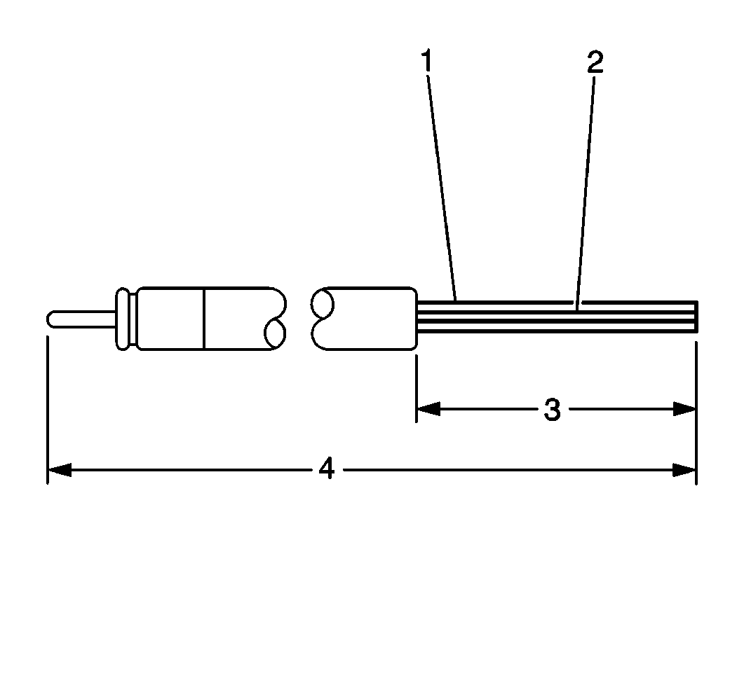
The noise sniffer, along
with the vehicle's radio, locates hot spots which generate noise interference.
These hot spots are found in the harness, in the upper part of the dash,
or even between the hood and the windshield. The sniffer may be made from
an old piece of antenna lead-in from a mast of a power antenna. The longer
the lead-in, the better (4). Make the noise sniffer as shown. The antenna
lead-in with the black coating and braided shield (2) stripped back becomes
the sniffer. When you plug the sniffer into the
radio's antenna socket, the sniffer probes and searches out hot spots.
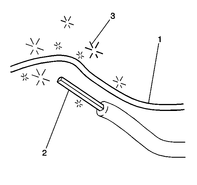
- Disconnect the antenna and plug the sniffer into the antenna socket
while you listen to the complaint noise.
- Turn the radio volume up.
- Search for the noise source (3). When you check for noise on
a wire, you get the best results when you place the sniffer (2) parallel
to the wire (1).
