Removal Procedure
Important: The wheel speed sensor and splash shield are replaced as one part. Do not attempt to separate and reattach the sensor from the splash shield.
Important: This vehicle is equipped with a either a 7300 lb. GVW (C6A), 7700 lb. GVW (C3F) or 8600 lb. GVW (C6P) suspension system. The 7300 lb. vehicle uses a stamped/welded upper control arm, and the 7700 lb. and 8600 lb. vehicles use a steel bar type upper control arm. The wheel speed sensor harness wire is attached and routed over the upper control arm in two different ways. Careful attention to these differences should be noted before removing any components, to assure proper reassembly.
- Raise and support vehicle.
- Remove the tire and wheel. Refer to Tire and Wheel Removal and Installation .
- Remove the brake caliper. Refer to Brake Caliper Replacement .
- Remove the hub and rotor. Refer to Brake Rotor Replacement .
- Disconnect the wheel speed sensor electrical connector and detach the rosebud clip from the frame.
- Remove bolt (9,15) and washer which attaches the sensor wire clip at the shock tower .
- Remove the rosebud clip (2) on upper control arm (3) (7300 lb. GVW (C6A) only).
- Remove the bolt (7,14) and nut (4,11) which attaches the sensor wire clip (2,9) at the upper ball joint (5,12) .
- Remove the splash shield mounting bolts (4).
- Remove the wheel speed sensor and splash shield assembly.
- Remove the splash shield gasket (5).
- Clean the gasket (5) and knuckle surfaces (6) thoroughly with a clean dry cloth.
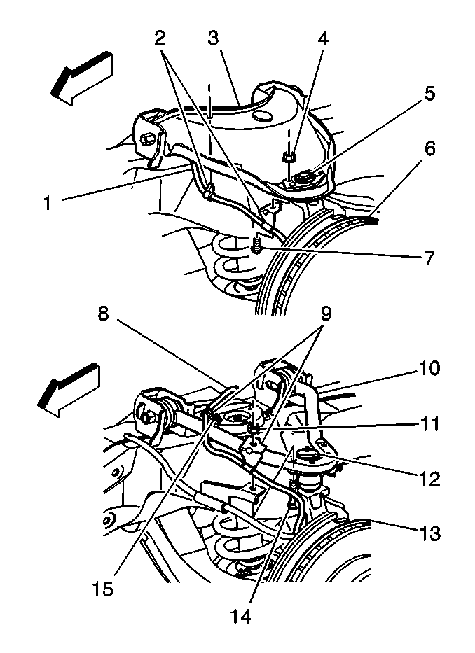
Important: Notice the position of the sensor wire clip on the shock tower. The sensor wire clip must be reinstalled in the same position, at approxomately 45° angle to the centerline of the vehicle.
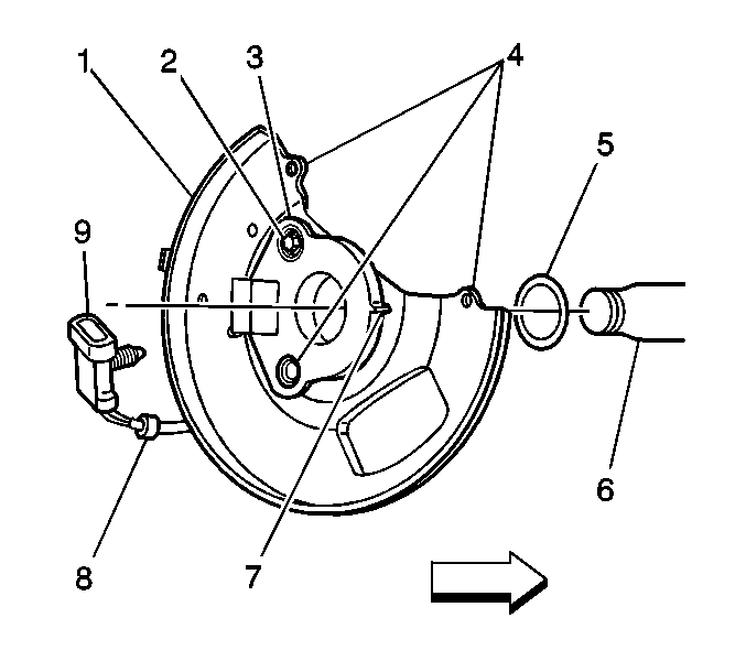
Important: The WSS (3) is held in place to the splash shield (1) with a plastic alignment tab (7) and a nut/bolt (2), located at the top hole in the WSS. It is not necessary to remove the top WSS bolt/nut (2) in order to remove the the wheel speed sensor and splash shield assembly.
Installation Procedure
- Install the splash shield gasket (5) on the knuckle spindle (6).
- Install wheel speed sensor and splash shield assembly.
- Install splash shield mounting bolts (4).
- Install the sensor wire clip (2,9) at the upper ball joint (5,12).
- Install the harness rosebud clip (2) at the upper control arm (3) (7300 lb. GVW (C6A) only).
- Install the sensor wire clip (15) at the shock tower bolt (8).
- Attach the wheel speed sensor connector to the inner frame rail with the connector mounted rosebud clip.
- Connect the wheel speed sensor connector to the vehicle harness.
- Install the hub and rotor. Refer to Brake Rotor Replacement .
- Install brake caliper. Refer to Brake Caliper Replacement .
- Install tire and wheel. Refer to Tire and Wheel Removal and Installation .
- Perform road test, driving the vehicle at speed greater than 32 km/h (20 mph).
- Using the Scan Tool, clear DTCs, then check Data List to verify wheel speeds.
Notice: Use the correct fastener in the correct location. Replacement fasteners must be the correct part number for that application. Fasteners requiring replacement or fasteners requiring the use of thread locking compound or sealant are identified in the service procedure. Do not use paints, lubricants, or corrosion inhibitors on fasteners or fastener joint surfaces unless specified. These coatings affect fastener torque and joint clamping force and may damage the fastener. Use the correct tightening sequence and specifications when installing fasteners in order to avoid damage to parts and systems.
Tighten
Tighten splash shield mounting bolts to 26 N·m (19 lb ft).
Tighten
Tighten wheel sensor wire clip nut (4,11) and bolt (7,14) to 17 N·m
(13 lb ft).
Important: Make sure that the position of the shock tower sensor wire clip is positioned at approxomately 45° angle to the centerline of the vehicle.
Tighten
Tighten the shock tower bolt to 15 N·m (11 lb ft).
