Hydraulic Brake System Bleeding Manual Bleeding
If air has entered the hydraulic brake system, bleed the
system. You may need to bleed the hydraulic brake system at all four wheels
due to one of the following conditions:
| • | Air entered the system due to a low fluid level. |
| • | The brake pipes have been disconnected at the master cylinder. |
| • | The brake pipes have been disconnected at the combination valve. |
If a pipe is disconnected at one wheel, then only bleed that wheel.
If the master cylinder has been removed, bleed the master cylinder before
installing it on the vehicle. This will reduce the time required to bleed
the system. Refer to
Master Cylinder Bench Bleeding
.
Notice: Brake fluid will damage electrical connections and painted surfaces.
Use shop cloths, suitable containers, and fender covers to prevent brake fluid
from contacting these areas. Always re-seal and wipe off brake fluid containers
to prevent spills.
Tools Required
J 28434 Wheel Cylinder
Bleeder Wrench
- If the vehicle has a vacuum booster, apply the brakes several
times with the ignition OFF. This relieves the vacuum reserve.
- Fill the master cylinder reservoir. Use Delco Supreme 11®
Hydraulic Brake Fluid GM P/N 12377967, or equivalent DOT 3 motor vehicle
brake fluid.
Maintain the fluid level during bleeding.
- If the master cylinder has air in the bore, bleed the master cylinder
using the following procedure:
| 3.2. | Allow the brake fluid to flow from the connector port. |
| 3.3. | Connect the brake pipe connector. Do not tighten the brake pipe
connector. |
| 3.4. | Slowly apply the brake pedal. Allow the air to bleed from the
loose connector. |
| 3.5. | Tighten the connector before releasing the brake pedal. |
| 3.7. | Repeat this sequence, including the 15-second wait, until you
purge all the air from the master cylinder bore. |
| 3.8. | Repeat this procedure for the rear brake pipe after you purge
all the air from the forward pipe connection. |
- If you replaced the Electronic Brake Control Module system, or
if you suspect that air is trapped inside, bleed the Electronic Brake Control
Module system next. Refer to
Antilock Brake System Automated Bleed Procedure
in Antilock Brake System.
- Bleed each wheel cylinder in the following sequence using J 28434
:
| 5.1. | Right rear wheel cylinder. |
| 5.2. | Left rear wheel cylinder. |
| 5.3. | Right front wheel caliper. |
| 5.4. | Left front wheel caliper. |
- Attach a hose to the wheel cylinder or caliper bleeder valve.
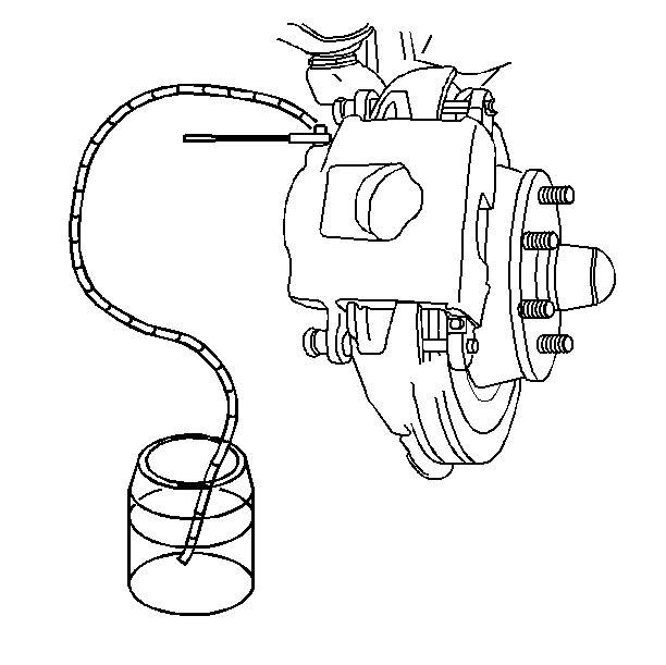
- Immerse the opposite
end of the hose into a container partially filled with clean brake fluid.
- Slowly apply the brake pedal one time and hold.
- Loosen the bleeder valve in order to purge the air from the wheel
cylinder or caliper.
Notice: Use the correct fastener in the correct location. Replacement fasteners
must be the correct part number for that application. Fasteners requiring
replacement or fasteners requiring the use of thread locking compound or sealant
are identified in the service procedure. Do not use paints, lubricants, or
corrosion inhibitors on fasteners or fastener joint surfaces unless specified.
These coatings affect fastener torque and joint clamping force and may damage
the fastener. Use the correct tightening sequence and specifications when
installing fasteners in order to avoid damage to parts and systems.
- Tighten the bleeder
valve.
Tighten
Tighten the bleeder valve to 13 N·m (110 lb in).
- Slowly release the brake pedal.
- Wait 15 seconds.
- Repeat this sequence, including the 15-second wait, until
you purge all the air from the wheel cylinder or caliper.
- Repeat steps 6-12 at each wheel until you purge all the
air from the brake system.
- Check for softness in the brake pedal action. Check the brake
warning lamp for an indication of unbalanced pressure. Repeat the bleeding
procedure in order to correct either of these conditions.
Hydraulic Brake System Bleeding Pressure Bleeding
If air has entered the hydraulic brake system, bleed the
system. You may need to bleed the hydraulic brake system at all four wheels
due to one of the following conditions:
| • | Air entered the system due to a low fluid level. |
| • | The brake pipes have been disconnected at the master cylinder. |
| • | The brake pipes have been disconnected at the combination valve. |
If a pipe is disconnected at one wheel, then only bleed that wheel.
If the master cylinder has been removed, bleed the master cylinder before
installing it on the vehicle. This will reduce the time required to bleed
the system. Refer to
Master Cylinder Bench Bleeding
.
Notice: Brake fluid will damage electrical connections and painted surfaces.
Use shop cloths, suitable containers, and fender covers to prevent brake fluid
from contacting these areas. Always re-seal and wipe off brake fluid containers
to prevent spills.
Tools Required
| • | J 28434 Wheel
Cylinder Bleeder Wrench |
Use a diaphragm-type pressure bleeder. The pressure bleeder must have
a rubber diaphragm between the air supply and the brake fluid. This prevents
air, moisture, oil and other contaminants from entering the brake hydraulic
system.
- Fill the pressure tank at least 2/3 full of brake fluid.
- Bleed the bleeder each time you add fluid.
- Charge the bleeder to 140-170 kPa (20-25 psi).
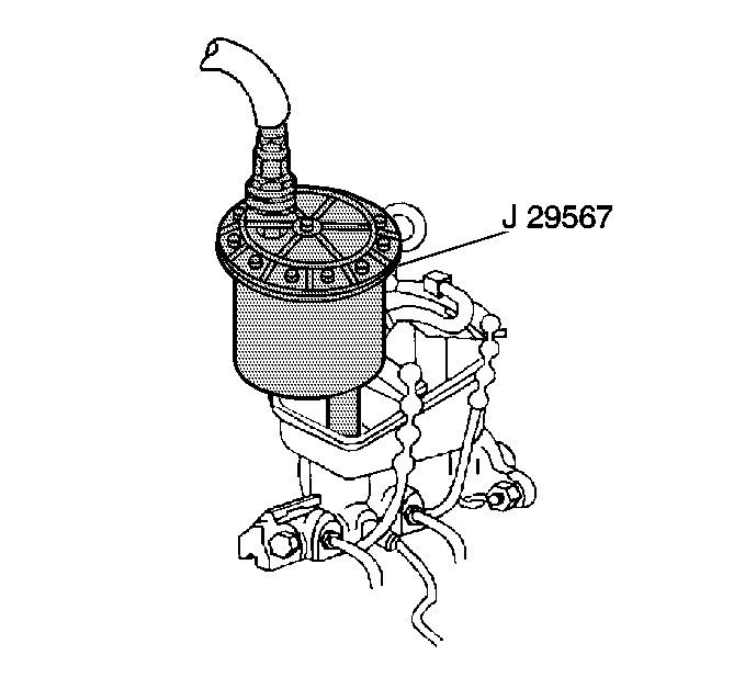
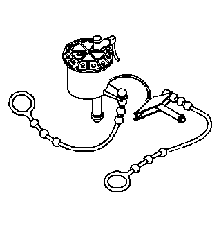
- Install the J 29567
.
- Bleed the Electronic Brake Control Module next if it has been
replaced, or if you suspect that air is trapped inside. Refer to
Antilock Brake System Automated Bleed Procedure
in Antilock Brakes.
- Bleed each wheel cylinder or caliper in the following sequence:
| 6.1. | Right rear wheel cylinder. |
| 6.2. | Left rear wheel cylinder. |
| 6.3. | Right front wheel caliper. |
| 6.4. | Left front wheel caliper. |
- Connect the hose from the bleeder to the adapter at the master
cylinder.
- Open the tank valve.
- Attach a hose to the bleeder valve.
- Immerse the opposite
end of the hose into a container partially filled with clean brake fluid.
Notice: Use the correct fastener in the correct location. Replacement fasteners
must be the correct part number for that application. Fasteners requiring
replacement or fasteners requiring the use of thread locking compound or sealant
are identified in the service procedure. Do not use paints, lubricants, or
corrosion inhibitors on fasteners or fastener joint surfaces unless specified.
These coatings affect fastener torque and joint clamping force and may damage
the fastener. Use the correct tightening sequence and specifications when
installing fasteners in order to avoid damage to parts and systems.
- Slowly open the
bleeder valve at least 3/4 of a turn. Allow the fluid to flow until you see
no air in the fluid.
Tighten
Tighten the wheel cylinder or caliper bleeder valve to 13 N·m
(110 lb in).
- Repeat steps 7-12 at every wheel.
- Check for softness in the brake pedal action. Repeat the bleeding
procedure if the brake pedal action is soft.
- Disconnect the hose from the bleeder adapter.
- Remove the J 29567
.
- Fill the master cylinder to the proper level. Refer to
Master Cylinder Reservoir Filling
in Hydraulic
Brakes.
