GM Service Manual Online
For 1990-2009 cars only
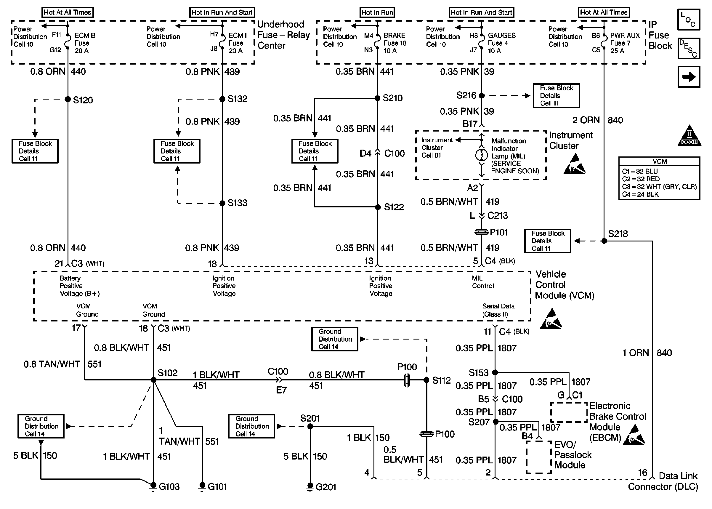
Figure 1:

Cell 20: PWR, GND and DLC


Object Number: 174868  Size: FS
Engine Controls Components
Information Sensors/Switches Description
Cell 20: Ignition Controls
OBD II Symbol Description Notice
Handling ESD Sensitive Parts Notice
VCM Connector End Views
Fuse Block Schematics
Ground Distribution Schematics
Power Distribution Schematics
Instrument Cluster: Analog Schematics
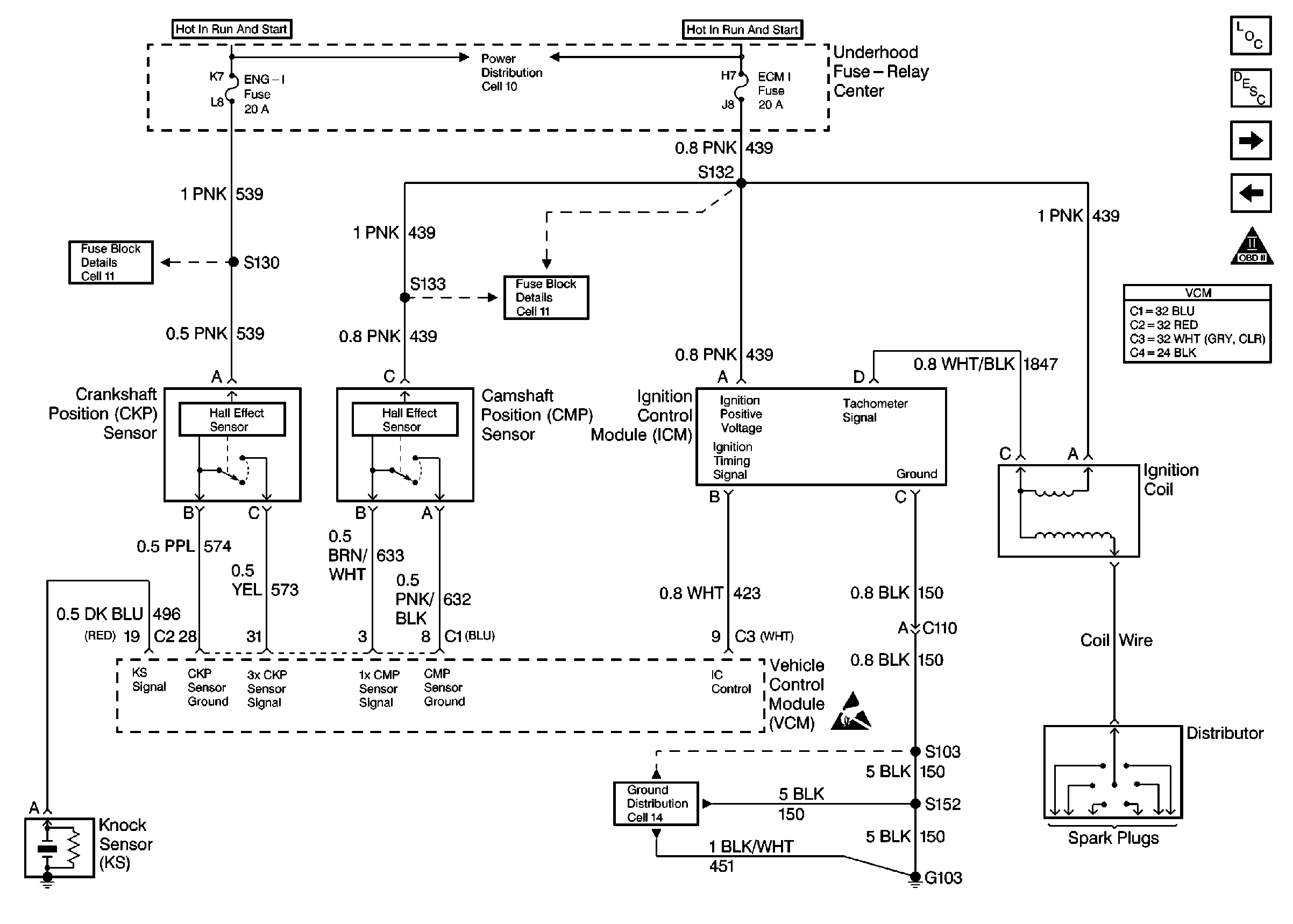
Figure 2:

Cell 20: Ignition Controls


Object Number: 174870  Size: FS
Engine Controls Components
Information Sensors/Switches Description
Cell 20: Fuel Pump Controls
Cell 20: PWR, GND and DLC
OBD II Symbol Description Notice
Handling ESD Sensitive Parts Notice
VCM Connector End Views
Fuse Block Schematics
Ground Distribution Schematics
Power Distribution Schematics
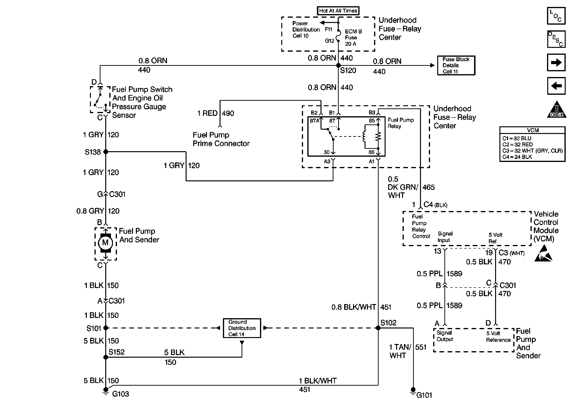
Figure 3:

Cell 20: Fuel Pump Controls


Object Number: 174877  Size: FS
Engine Controls Components
Information Sensors/Switches Description
Cell 20: Fuel Injector Controls
Cell 20: Ignition Controls
OBD II Symbol Description Notice
Handling ESD Sensitive Parts Notice
VCM Connector End Views
Power Distribution Schematics
Fuse Block Schematics
Ground Distribution Schematics
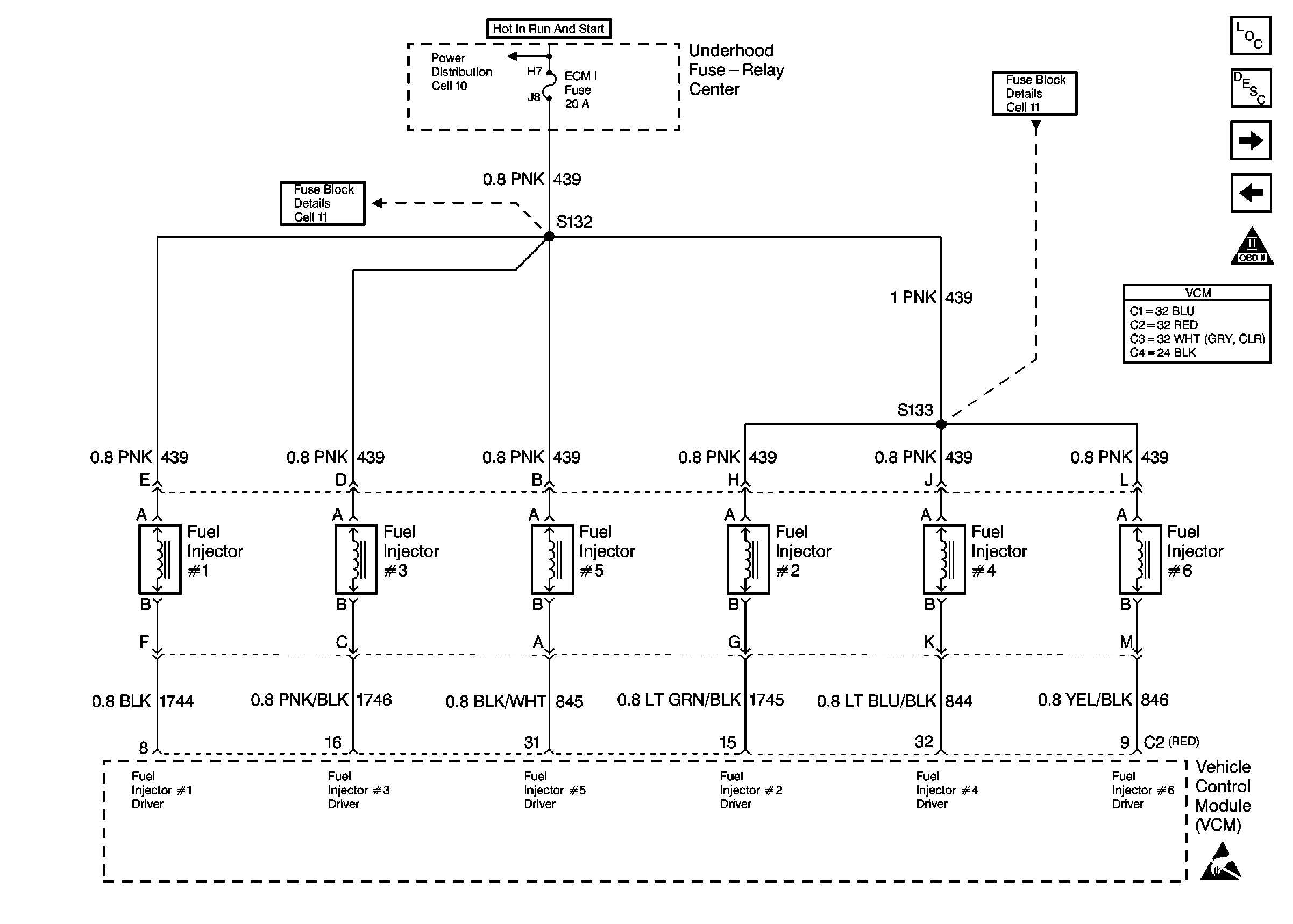
Figure 4:

Cell 20: Fuel Injector Controls


Object Number: 174884  Size: FS
Engine Controls Components
Information Sensors/Switches Description
Cell 20: Sensor Controls
Cell 20: Fuel Pump Controls
OBD II Symbol Description Notice
Handling ESD Sensitive Parts Notice
VCM Connector End Views
Power Distribution Schematics
Fuse Block Schematics
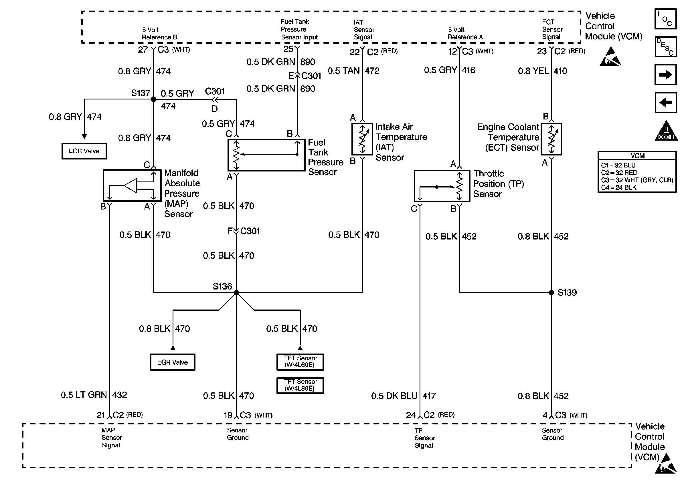
Figure 5:

Cell 20: Sensor Controls


Object Number: 174887  Size: FS
Engine Controls Components
Information Sensors/Switches Description
Cell 20: EGR and EVAP Controls
Cell 20: Fuel Injector Controls
OBD II Symbol Description Notice
Cell 20: EGR and EVAP Controls
Cell 20: 4L60-E Transmission Switch Controls
Cell 20: 4L80-E Transmission Switch Controls
Handling ESD Sensitive Parts Notice
VCM Connector End Views
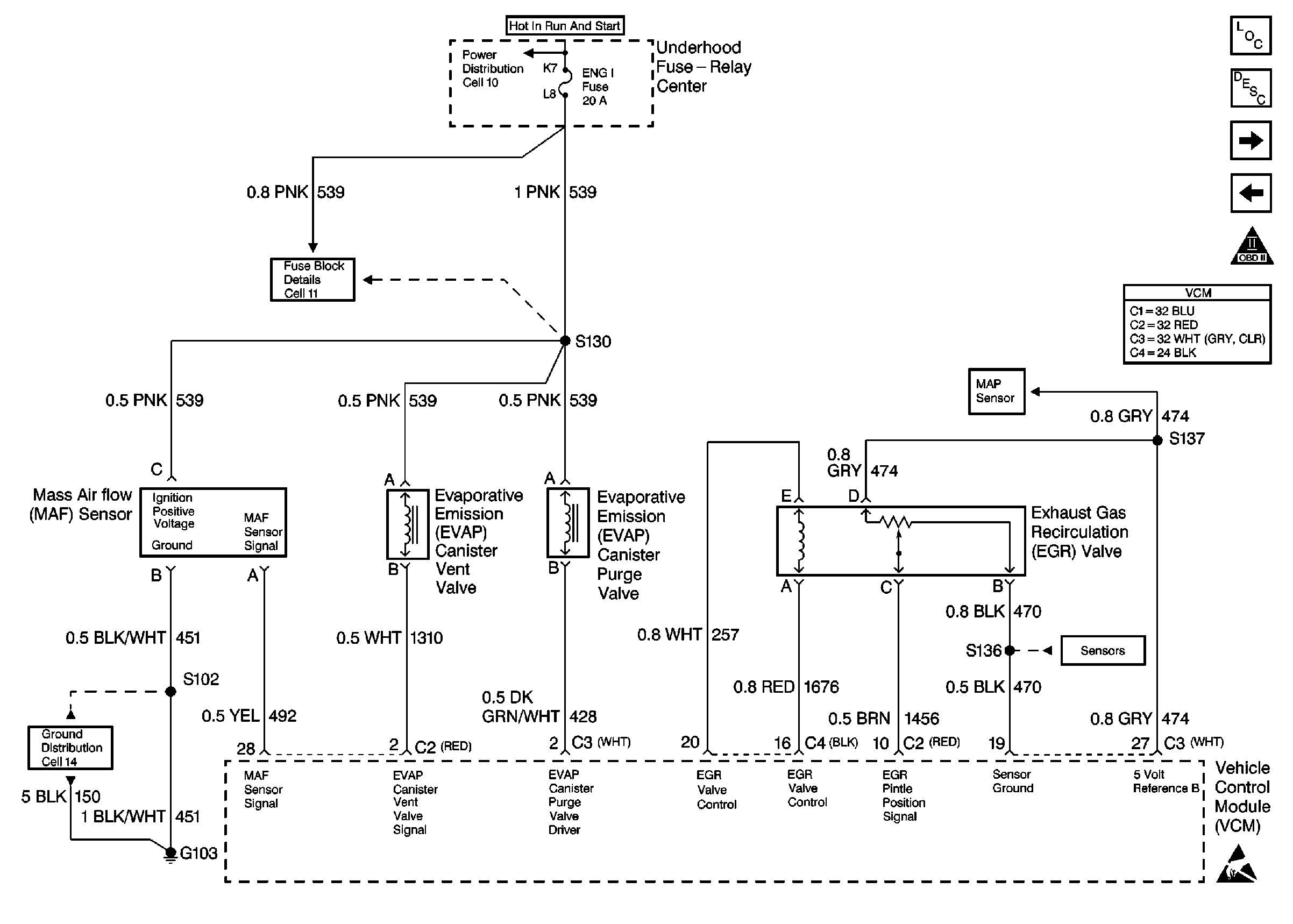
Figure 6:

Cell 20: EGR and EVAP Controls


Object Number: 174927  Size: FS
Engine Controls Components
Information Sensors/Switches Description
Cell 20: Sensor Controls
Cell 20: Oxygen Sensor Controls
OBD II Symbol Description Notice
Cell 20: Sensor Controls
Handling ESD Sensitive Parts Notice
VCM Connector End Views
Power Distribution Schematics
Fuse Block Schematics
Ground Distribution Schematics
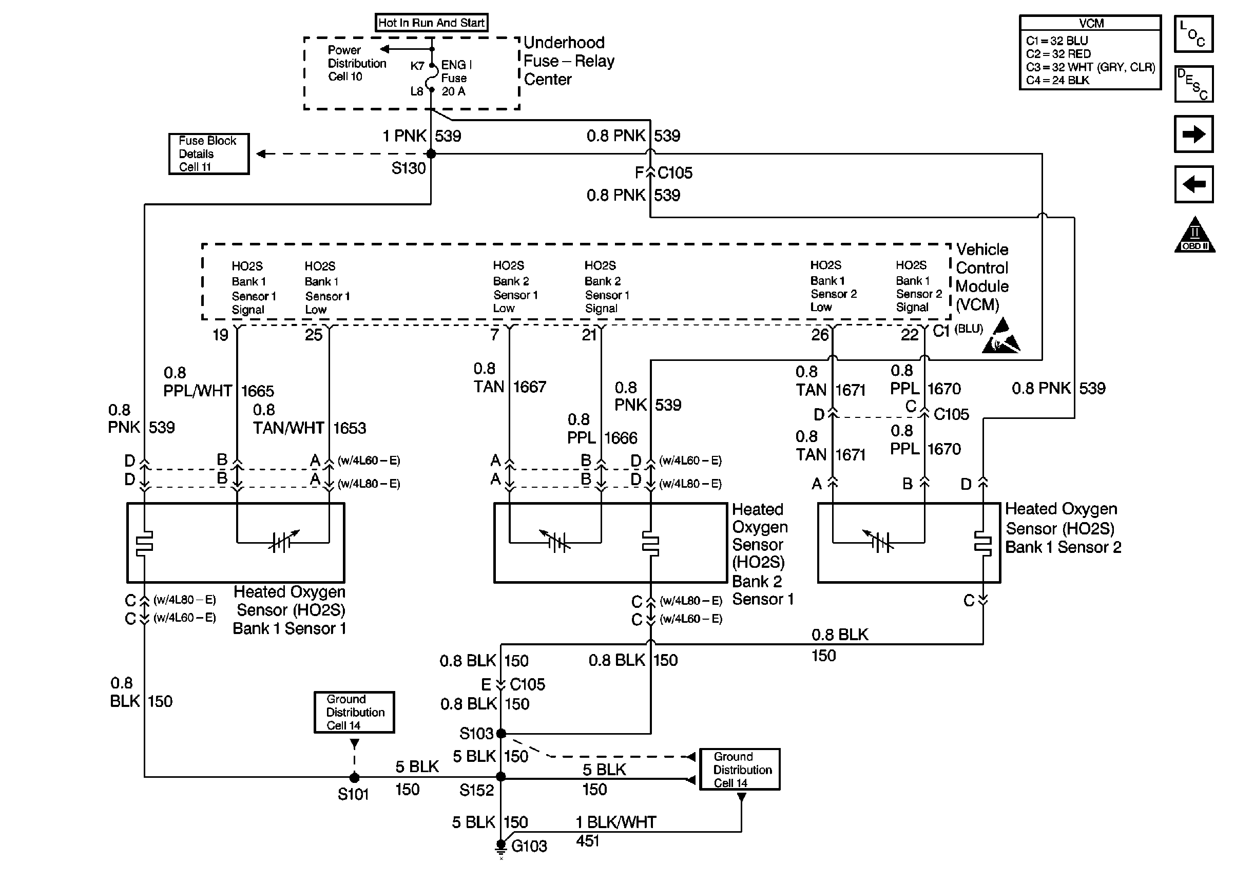
Figure 7:

Cell 20: Oxygen Sensor Controls


Object Number: 174928  Size: FS
Engine Controls Components
Information Sensors/Switches Description
Cell 20: VSS and Cruise Controls
Cell 20: EGR and EVAP Controls
OBD II Symbol Description Notice
Handling ESD Sensitive Parts Notice
VCM Connector End Views
Power Distribution Schematics
Fuse Block Schematics
Ground Distribution Schematics
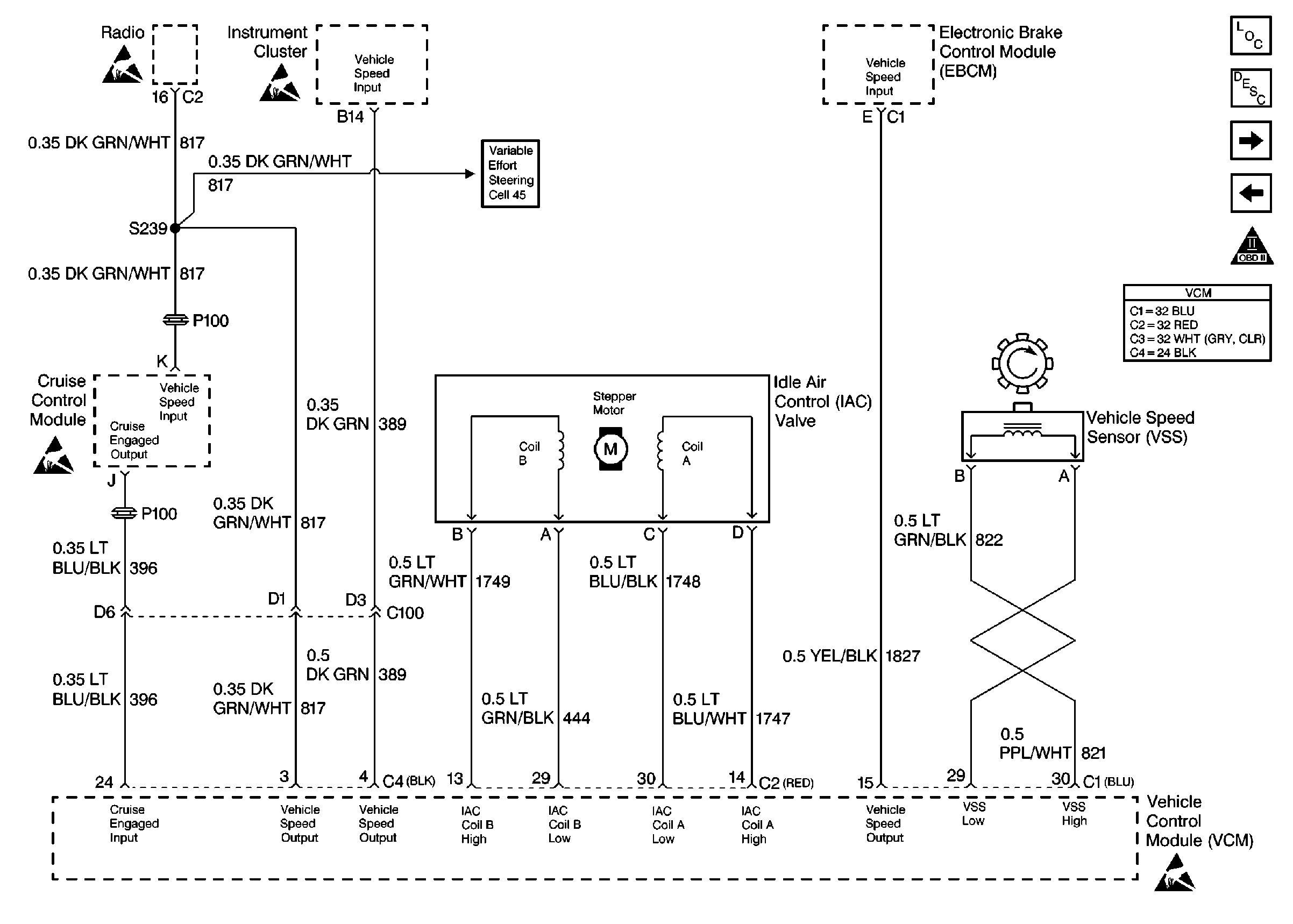
Figure 8:

Cell 20: VSS and Cruise Controls


Object Number: 174929  Size: FS
Engine Controls Components
Information Sensors/Switches Description
Cell 20: 4L60-E Transmission Solenoid Controls
Cell 20: Sensor Controls
OBD II Symbol Description Notice
Handling ESD Sensitive Parts Notice
VCM Connector End Views
Steering Assist Schematics
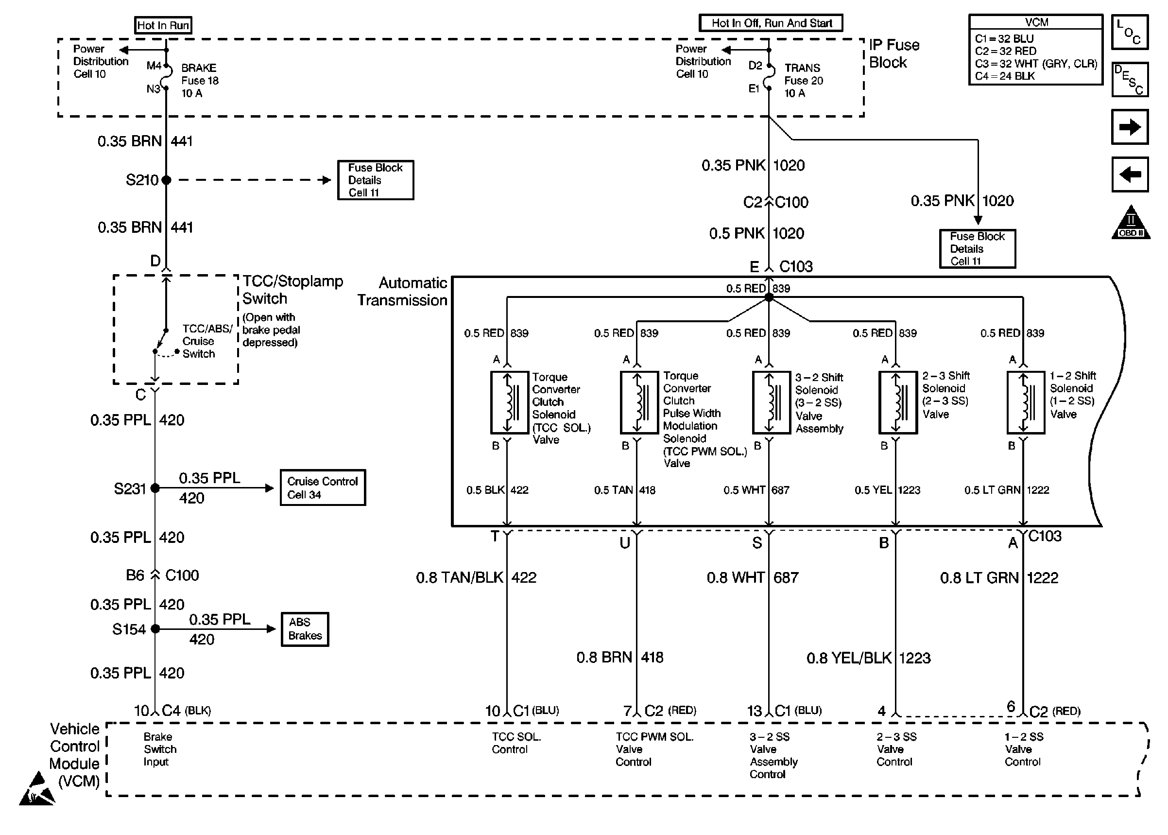
Figure 9:

Cell 20: 4L60-E Transmission Solenoid Controls


Object Number: 174930  Size: FS
Engine Controls Components
Information Sensors/Switches Description
Cell 20: 4L60-E Transmission Switch Controls
Cell 20: VSS and Cruise Controls
OBD II Symbol Description Notice
Handling ESD Sensitive Parts Notice
VCM Connector End Views
Power Distribution Schematics
Fuse Block Schematics
Cruise Control Schematics
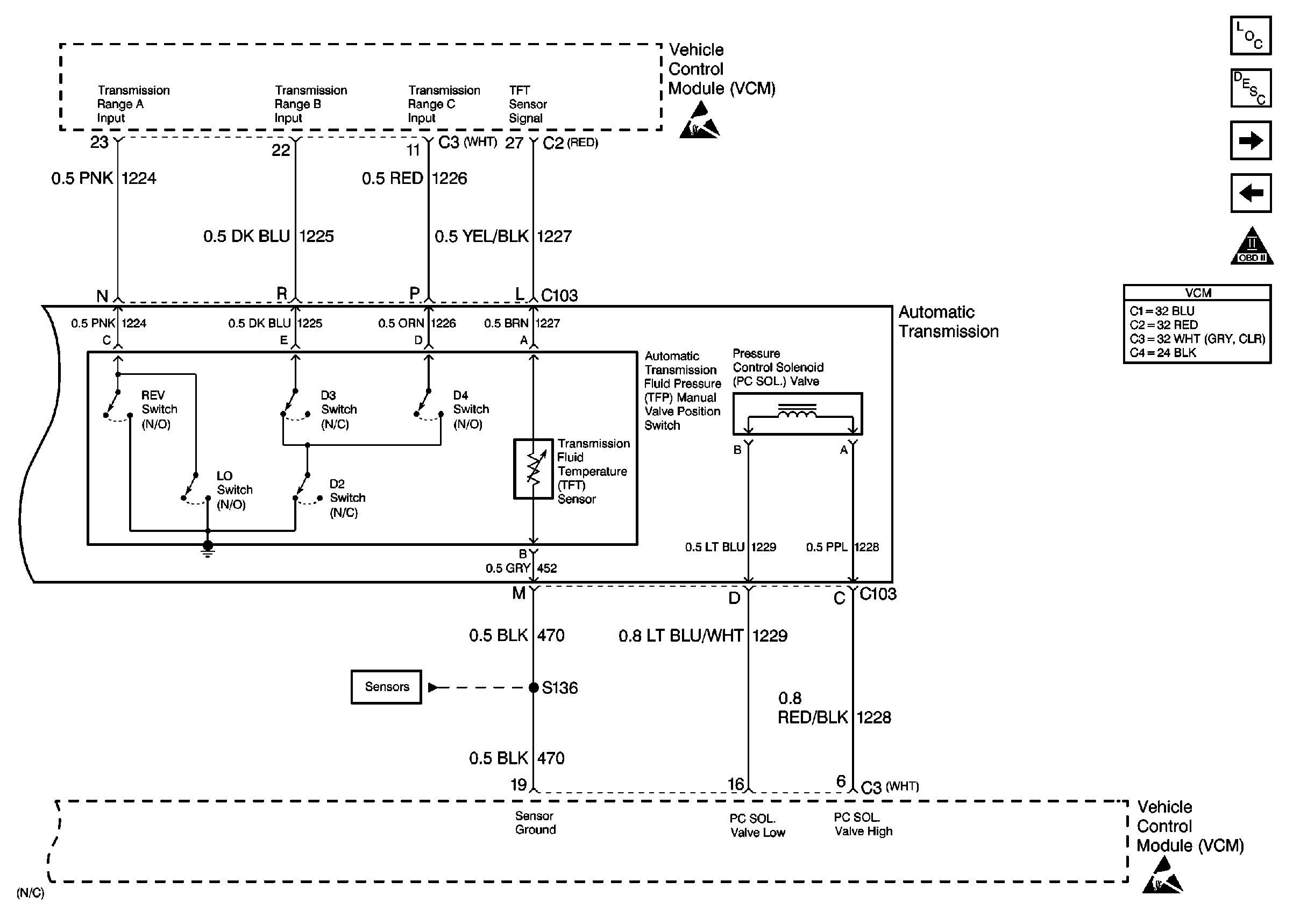
Figure 10:

Cell 20: 4L60-E Transmission Switch Controls


Object Number: 174932  Size: FS
Engine Controls Components
Information Sensors/Switches Description
Cell 20: 4L80-E Transmission Solenoid Controls
Cell 20: 4L60-E Transmission Solenoid Controls
OBD II Symbol Description Notice
Cell 20: Sensor Controls
Engine Controls Schematic Icons
VCM Connector End Views
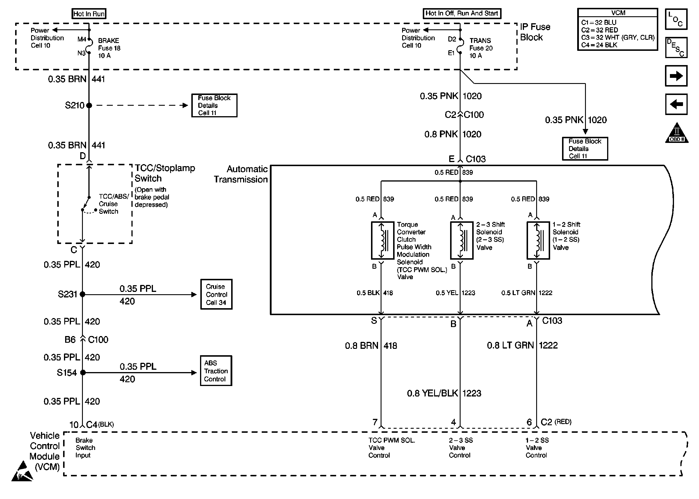
Figure 11:

Cell 20: 4L80-E Transmission Solenoid Controls


Object Number: 174934  Size: FS
Engine Controls Components
Information Sensors/Switches Description
Cell 20: 4L80-E Transmission Switch Controls
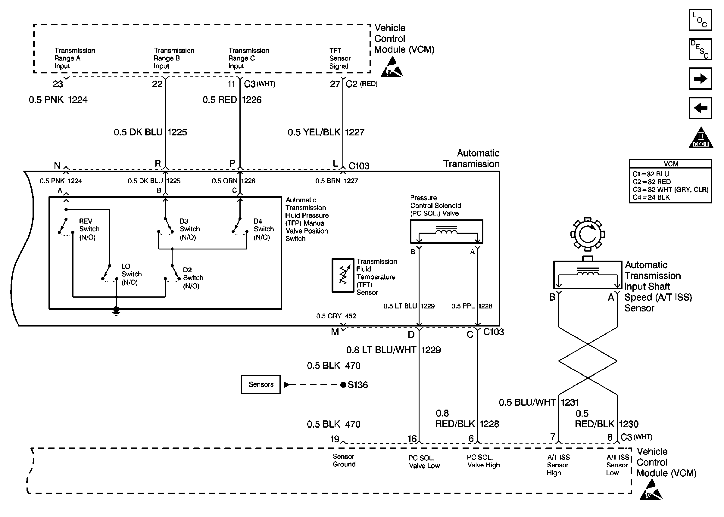
Cell 20: 4L60-E Transmission Switch Controls
OBD II Symbol Description Notice
Engine Controls Schematic Icons
VCM Connector End Views
Figure 12:

Cell 20: 4L80-E Transmission Switch Controls


Object Number: 174936  Size: FS
Engine Controls Components
Information Sensors/Switches Description
Cell 20: A/C Controls
Cell 20: 4L80-E Transmission Solenoid Controls
OBD II Symbol Description Notice
Cell 20: Sensor Controls
Engine Controls Schematic Icons
VCM Connector End Views
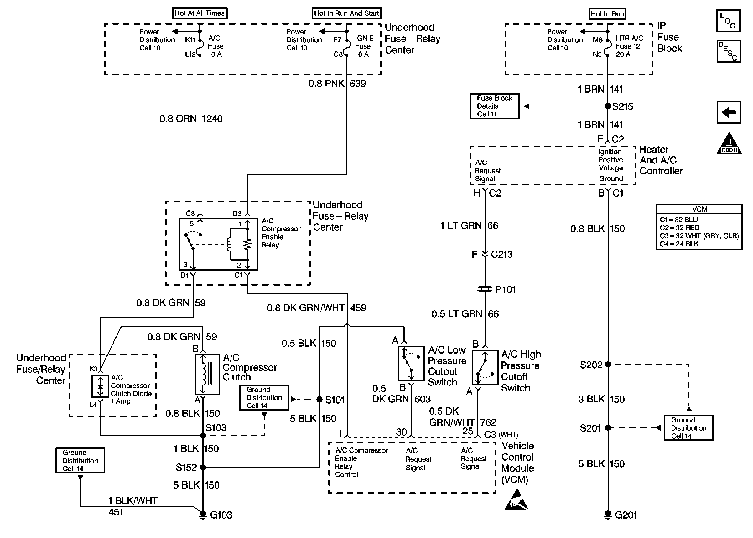
Figure 13:

Cell 20: A/C Controls


Object Number: 174937  Size: FS
Engine Controls Components
Information Sensors/Switches Description
Cell 20: 4L80-E Transmission Switch Controls
OBD II Symbol Description Notice
Engine Controls Schematic Icons
VCM Connector End Views