Intake Manifold Replacement Upper
Removal Procedure
- Open the hood.
- Disconnect the battery negative cable from the battery. Refer to Battery Cable Replacement in Engine Electrical.
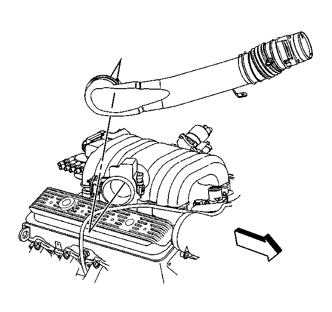
- Remove the air intake duct from the throttle body. Refer to Air Intake Duct Replacement in Engine Controls-7.4L.
- Remove the air cleaner assembly from vehicle. Refer to Air Cleaner Assembly Replacement in Engine Controls-7.4L.
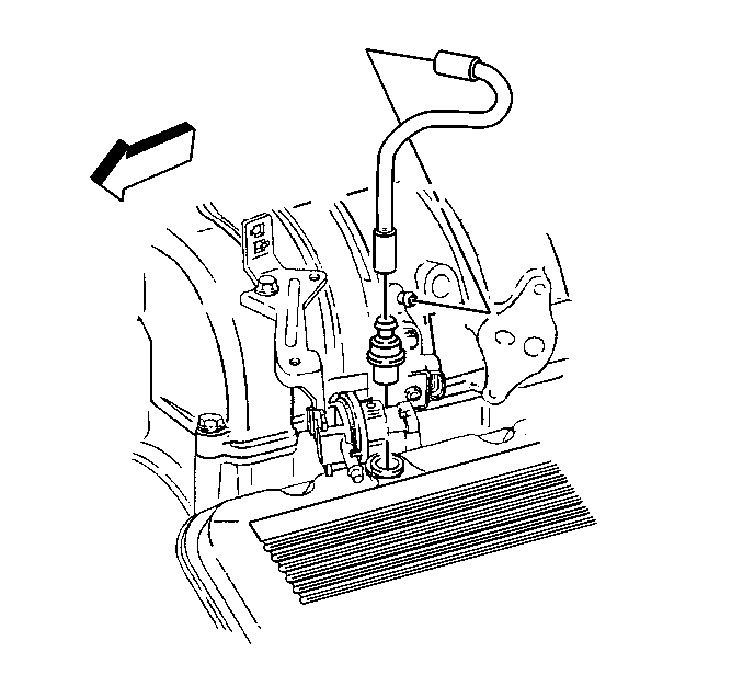
- Remove the crankcase vent tube from the throttle body.
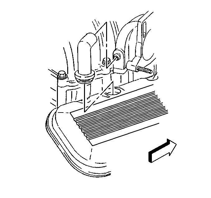
- Remove the PCV valve from the valve rocker arm cover.
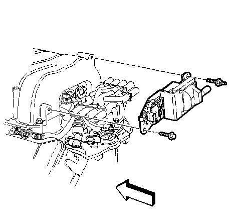
- Remove the EGR pipe from the upper intake manifold. Refer to Exhaust Gas Recirculation Valve Replacement .
- Remove the ignition coil from the intake manifold. Refer to Ignition Coil and Ignition Coil Module Replacement .
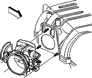
- Remove the throttle body from the upper intake manifold. Refer to Throttle Body Assembly Replacement .
- Remove the EVAP canister solenoid valve. Refer to EVAP Canister Solenoid Replacement in Engine Controls-7.4L.
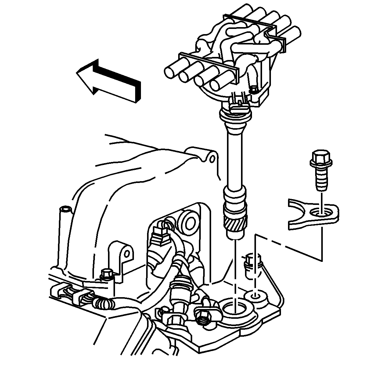
- Remove the number 8 spark plug wire from the distributor. Refer to Spark Plug Wire Harness Replacement .
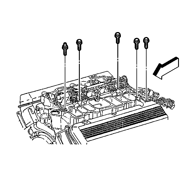
- Remove the upper intake manifold bolts.
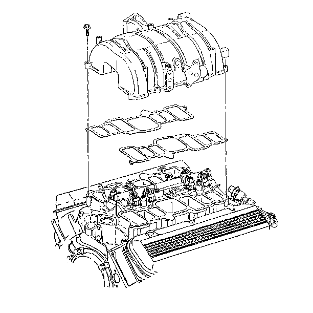
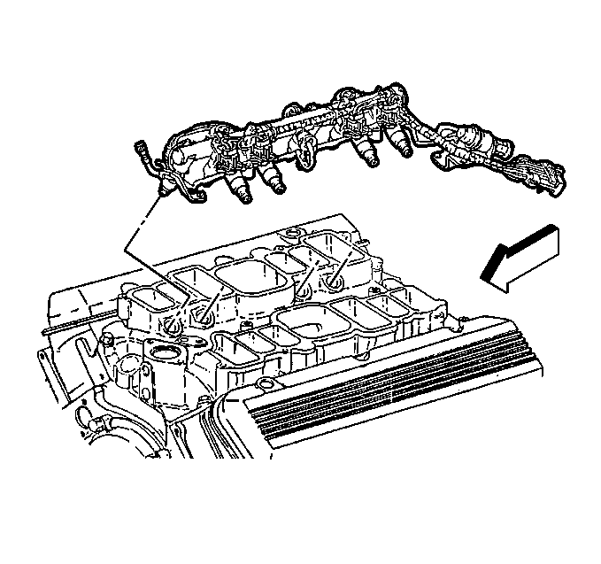
- Remove the upper intake manifold and gaskets from the lower intake manifold.
- Clean the excessive carbon deposit from the exhaust and the EGR valve passages.
Caution: Before servicing any electrical component, the ignition and start switch must be in the OFF or LOCK position and all electrical loads must be OFF, unless instructed otherwise in these procedures. If a tool or equipment could easily come in contact with a live exposed electrical terminal, also disconnect the negative battery cable. Failure to follow these precautions may cause personal injury and/or damage to the vehicle or its components.
Installation Procedure
- Install the upper intake manifold and gaskets to the lower intake manifold.
- Coat a minimum of eight threads of the bolts with thread locking sealant G/M P/N 12345493.
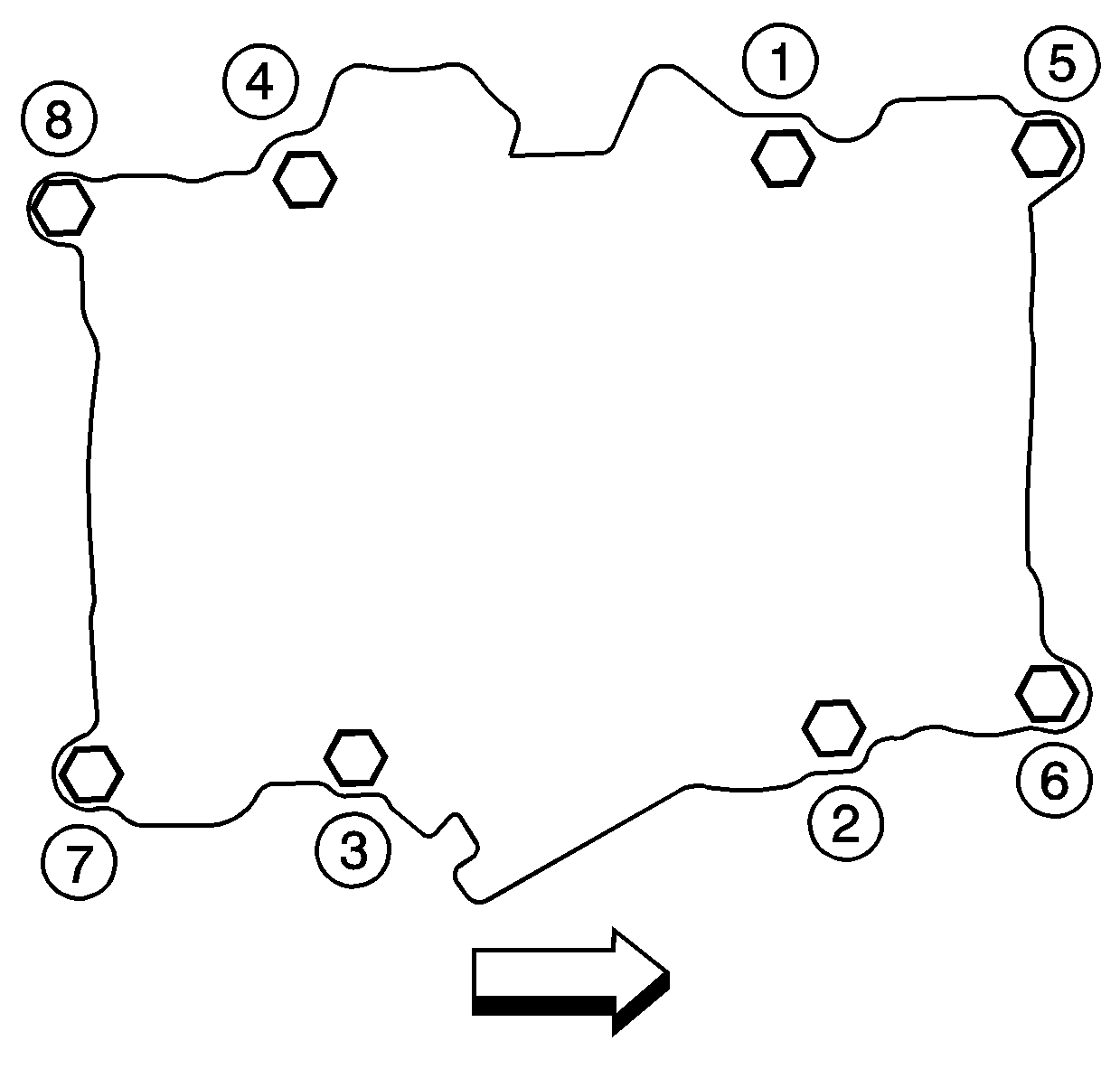
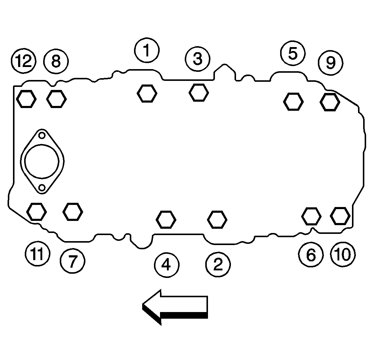
- Install the upper intake manifold bolts and tighten in the following manner.
- Tighten the bolts in sequence to 8 N·m (72 lb in).
- Re tighten the bolts in sequence to 18 N·m (13 lb ft).
- Install the number 8 spark plug wire. Refer to Spark Plug Wire Harness Replacement .
- Install the ignition coil to the upper intake manifold. Refer to Ignition Coil and Ignition Coil Module Replacement .
- Install the EGR valve if necessary. Refer to Exhaust Gas Recirculation Valve Replacement .
- Install the EGR pipe to the upper intake manifold. Refer to EGR Pipe Replacement in Engine Controls--7.4L.
- Install the EVAP canister solenoid valve to the intake manifold. Refer to EVAP Canister Solenoid Replacement in Engine Controls-7.4L.
- Install the throttle body to the upper intake manifold. Refer to Throttle Body Assembly Replacement .
- Install the PCV valve to the valve rocker arm cover to the cylinder head.
- Install the crankcase vent tube to the valve rocker arm cover.
- Install the air intake duct to the throttle body. Refer to Air Intake Duct Replacement in Engine Controls -7.4L.
- Connect the battery negative cables to the battery. Refer to Battery Cable Replacement in Engine Electrical.
- Close the hood.
Important: Failure to follow the procedure listed, could cause a driveability problem.
Notice: Use the correct fastener in the correct location. Replacement fasteners must be the correct part number for that application. Fasteners requiring replacement or fasteners requiring the use of thread locking compound or sealant are identified in the service procedure. Do not use paints, lubricants, or corrosion inhibitors on fasteners or fastener joint surfaces unless specified. These coatings affect fastener torque and joint clamping force and may damage the fastener. Use the correct tightening sequence and specifications when installing fasteners in order to avoid damage to parts and systems.
Tighten
Tighten
Tighten EGR valve fittings to 60 N·m (46 lb ft).
Intake Manifold Replacement Lower
Removal Procedure
Important: The lower intake manifold gaskets and seals are reusable. Replace only the gaskets and seals if they are damaged.
- Open the hood.
- Remove the engine cover from the vehicle. Refer to Engine Cover Replacement in Interior Trim.
- Drain the cooling system. Refer to Cooling System Draining and Filling .
- Disconnect the battery negative cable from the battery.
- Remove the upper intake manifold from the lower intake manifold. Refer to Intake Manifold Replacement .
- Remove the suction line from Air Conditioning from the A/C compressor. Refer to Suction Line Replacement in HVAC.
- Remove the distributor from the lower intake manifold. Refer to Distributor Replacement .
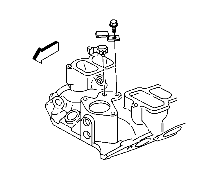
- Remove the MAP sensor from the lower intake manifold. Refer to Manifold Absolute Pressure Sensor Replacement .
- Remove the radiator hose from the thermostat. Refer to Radiator Hose Replacement .
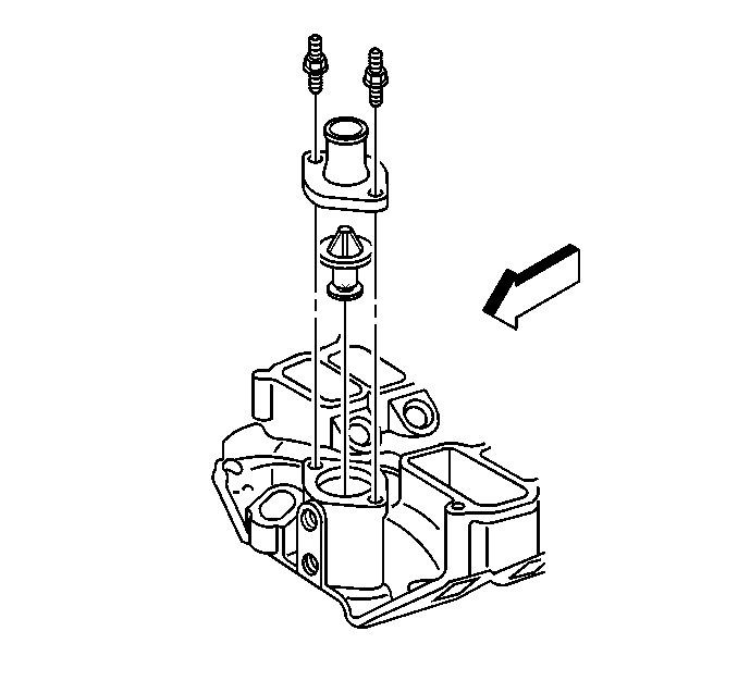
- Remove the thermostat housing from the lower intake manifold from the engine block. Refer to Engine Coolant Thermostat Replacement .
- Remove the heater hoses from the heater core.
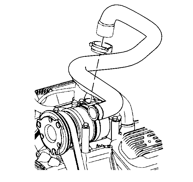
- Remove the coolant bypass hose from the lower intake manifold and the water pump.
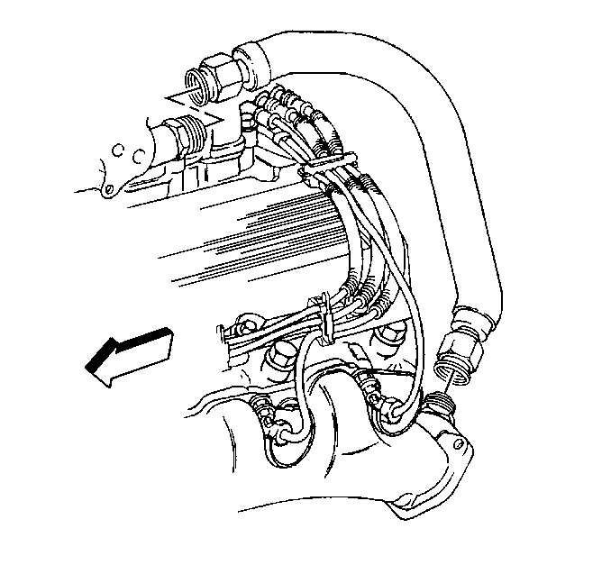
- Remove the retaining bolts for the fuel rail. Refer to Fuel Hose/Pipes Replacement - Engine Compartment .
- Remove the fuel rail from the lower intake manifold. Refer to Fuel Hose/Pipes Replacement - Engine Compartment .
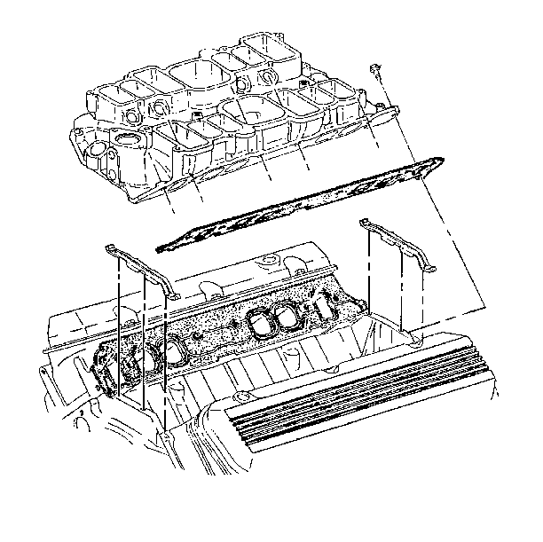
- Remove the lower intake manifold bolts from the engine head.
- Remove the lower intake manifold from the cylinder head.
- Remove the lower intake manifold gaskets and seals from the cylinder head.
- Clean all sealing surfaces of oil and grease. Refer to Intake Manifold Cleaning and Inspection .
Caution: Before servicing any electrical component, the ignition and start switch must be in the OFF or LOCK position and all electrical loads must be OFF, unless instructed otherwise in these procedures. If a tool or equipment could easily come in contact with a live exposed electrical terminal, also disconnect the negative battery cable. Failure to follow these precautions may cause personal injury and/or damage to the vehicle or its components.
Important: Mark the relationship of the distributor housing to the rotor for proper reinstallation.
Installation Procedure
- Install the lower intake manifold gaskets to the cylinder head with THIS SIDE UP stamped facing up.
- Install the lower intake manifold to the engine block.
- Apply the Locttite® 242 GM P/N 12345382 to the lower intake manifold bolts.
- Install the lower intake manifold bolts to the engine head.
- Install the fuel rail to the lower intake manifold. Refer to Fuel Hose/Pipes Replacement - Engine Compartment .
- Install the fuel rail retaining bolts. Refer to Fuel Hose/Pipes Replacement - Engine Compartment .
- Install the coolant bypass hose to the water pump. Refer to Coolant Bypass hose Replacement in Engine Cooling.
- Install the heater hoses to the lower intake manifold. Refer to Heater Hose Replacement in Engine Cooling.
- Install the thermostat housing to the lower intake manifold from the engine block. Refer to Engine Coolant Thermostat Replacement .
- Install the MAP sensor to the lower intake manifold. Refer to Manifold Absolute Pressure Sensor Replacement .
- Install the radiator hose to the thermostat housing. Refer to Radiator Hose Replacement .
- Install the distributor to the engine block. Refer to Distributor Replacement .
- Install the suction hose to the A/C compressor. Refer to Suction Hose Replacement in HVAC.
- Install the upper intake manifold to the lower intake manifold. Refer to Intake Manifold Replacement .
- Install the discharge line to the A/C compressor. Refer to Discharger Line Replacement in HVAC.
- Refill the cooling system. Refer to Cooling System Draining and Filling .
- Connect the battery negative cable to the battery. Refer to Battery Cable Replacement in Engine Electrical.
- Close the hood.
Notice: Use the correct fastener in the correct location. Replacement fasteners must be the correct part number for that application. Fasteners requiring replacement or fasteners requiring the use of thread locking compound or sealant are identified in the service procedure. Do not use paints, lubricants, or corrosion inhibitors on fasteners or fastener joint surfaces unless specified. These coatings affect fastener torque and joint clamping force and may damage the fastener. Use the correct tightening sequence and specifications when installing fasteners in order to avoid damage to parts and systems.
Tighten
Tighten the bolts in sequence to 40 N·m (30 lb ft).
