Circuit Description
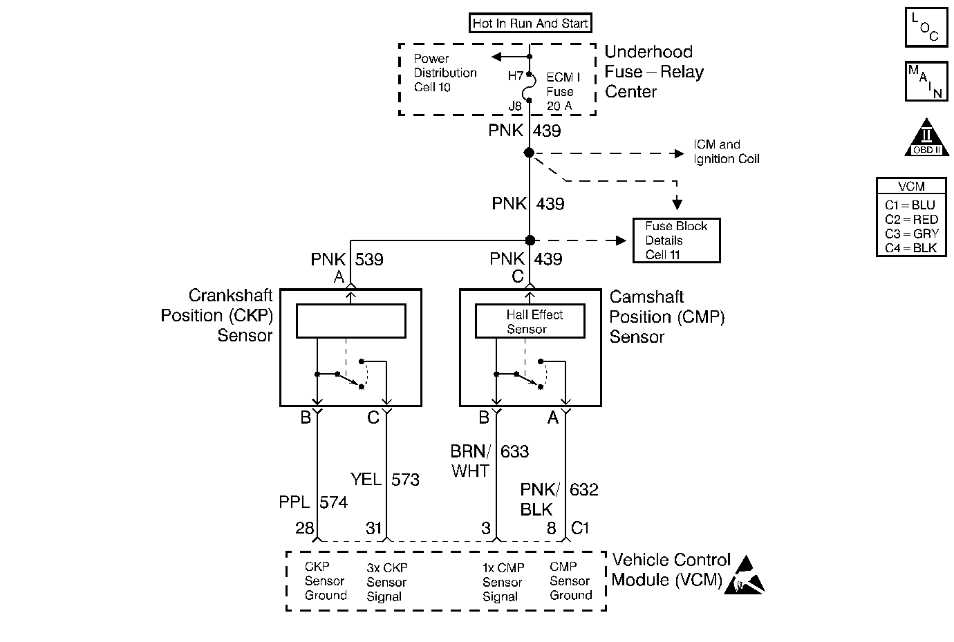
The crankshaft position (CKP) sensor and the camshaft position (CMP) sensor are used in order to detect an engine misfire. The VCM monitors the speed of the crankshaft. The VCM detects a deceleration of the crankshaft that is not associated with a normal engine speed reduction. In order to determine if a misfire occurred, the VCM compares the deceleration information to the engine speed and the engine load. If a misfire event is determined, the VCM compares the crankshaft position to the cam sensor signal in order to determine which cylinder misfired. The VCM stores the information in separate accumulators for each cylinder. Upon completion (or failure) of the test, the VCM evaluates the number of misfires in each accumulator. If the accumulators are somewhat even or if 3 or more cylinders are misfiring, then this determines that a random misfire has occurred. The VCM also utilizes the input from the ABS wheel speed sensor in order to determine if a rough road condition exists which could cause a crankshaft acceleration and deceleration. If a rough road condition exists, the diagnostic will not run. This DTC is a type B DTC.
Conditions for Setting the DTC
| • | No TP sensor DTCs |
| • | No MAP sensor DTCs |
| • | No Camshaft Position sensor DTCs |
| • | No Crankshaft Position sensor DTCs |
| • | ECT Sensor is greater than -7°C |
| • | The engine speed between 600 RPM and 5600 RPM |
| • | The system voltage between 9 volts and 16 volts |
| • | The positive throttle position change is less than 4.9% per 100 msec. |
| • | The negative throttle position change is less than 2.9% per 100 msec. |
Action Taken When the DTC Sets
If the VCM determines that the engine misfire is significant enough to have a negative impact on emissions, the VCM turns ON the malfunction indicator lamp (MIL) after the misfire has been detected on 2 non-consecutive trips under the same operating conditions. If the misfire is severe enough that catalytic converter damage could result, the MIL flashes while the misfire is present.
Conditions for Clearing the MIL/DTC
The VCM turns OFF the MIL after 3 consecutive driving trips without a fault condition present. A history DTC will clear if no fault conditions have been detected for 40 warm-up cycles (the coolant temperature has risen 22°C (40°F) from the start-up coolant temperature and the engine coolant temperature exceeds 71°C (160°F) during that same ignition cycle) or the scan tool clearing feature has been used.
Diagnostic Aids
The Misfire Index counts the number of misfires. The scan tool can monitor the Misfire Index. There is a current and history misfire counter for each cylinder. Use the current misfire counter in order to determine which cylinder is misfiring.
Many different condition could cause an intermittent misfire.
Check for the following conditions:
- Check the spark plug wires and the coil wire for the following conditions:
- Check for contaminated and a low fuel level and the following conditions:
| • | Ensure that the spark plug wires are securely attached to the spark plugs and the distributor cap. |
| • | Check the wire routing in order to ensure that crossfiring is not occurring. |
| • | If the misfire occurs when the weather is damp, the problem could be due to worn plug wires. |
| • | In order to test for this condition, spray the wires with water and with the engine running, watch for spark to jump from the wires. If a spark is visible, replace the wires. |
| • | Check the fuel condition and quality. Dirty or contaminated fuel could cause a misfire condition. |
| • | If the fuel level is low, contaminants in the bottom of the fuel tank could enter into the fuel metering system. |
For more information, refer to fuel supply system.
Test Description
The numbers below refer to the step numbers on the diagnostic table.
-
If DTCs P0337 (Crankshaft Position Sensor Circuit Low Input) or P0338 (Crankshaft Position Sensor Circuit - High Input) are set, this could result in a misfire condition.
-
In order to duplicate the conditions under which the misfire occurred, it may be necessary to drive the vehicle and monitor the scan tool DTC Set This Ignition Cycle variable.
-
When checking the spark at the spark plug wires, the spark should be consistent. A few sparks then nothing is no spark.
-
At this point, the ignition system is OK and the problem may be in the fuel system. Fuel System Diagnosis must be performed in order to determine the cause of the problem.
Step | Action | Value(s) | Yes | No |
|---|---|---|---|---|
1 |
Important: Before clearing the DTCs use the scan tool to record freeze frame and failure records for reference, as data will be lost when Clear Info function is used. Was the Powertrain On-Board Diagnostic (OBD) System Check performed? | -- | ||
Review Failure Records data. Are there any other DTCs stored? | -- | Go to Applicable DTC Table | ||
3 |
Is the MAP sensor voltage greater than the specified value? | 4.0 V | Go to DTC P0108 Manifold Absolute Pressure (MAP) Sensor Circuit High Voltage | |
Duplicate the conditions during which the misfire occurred. Is the DTC active at the ignition cycle? | -- | |||
Using a scan tool, review the Misfire Index. Is the Misfire Index increasing for more than one cylinder? | -- | Go to Diagnostic Aids | ||
6 |
Was the spark adequate on all of the spark plug wires? | -- | ||
Inspect the spark plugs for wear, excessive air gaps, cracks, or fouling. Are the spark plugs OK? | -- | |||
8 | Perform a cylinder compression test. Refer to Engine Mechanical. Was a problem found? | -- | ||
9 | Refer to Fuel System Diagnosis Is the fuel system OK? | -- | ||
10 | Misfire is intermittent and is currently not active. Go to the Diagnostic Aids. | -- | -- | -- |
11 | Refer to Enhanced Ignition System | -- | -- | -- |
12 | Replace the spark plugs. Is the action complete? | -- | -- | |
13 | Make repairs as indicated by the Fuel System Diagnosis. Refer to Fuel System Diagnosis . Is action complete? | -- | -- | |
14 |
Does the scan tool indicate that this diagnostic ran and passed? | -- | ||
15 | Using the scan tool, select Capture Info and Review Info. Are any DTCs displayed that have not been diagnosed? | -- | Go to the Applicable DTC Table | System OK |
