Refer to
Fuel Pump Controls 5.0L/5.7L
.
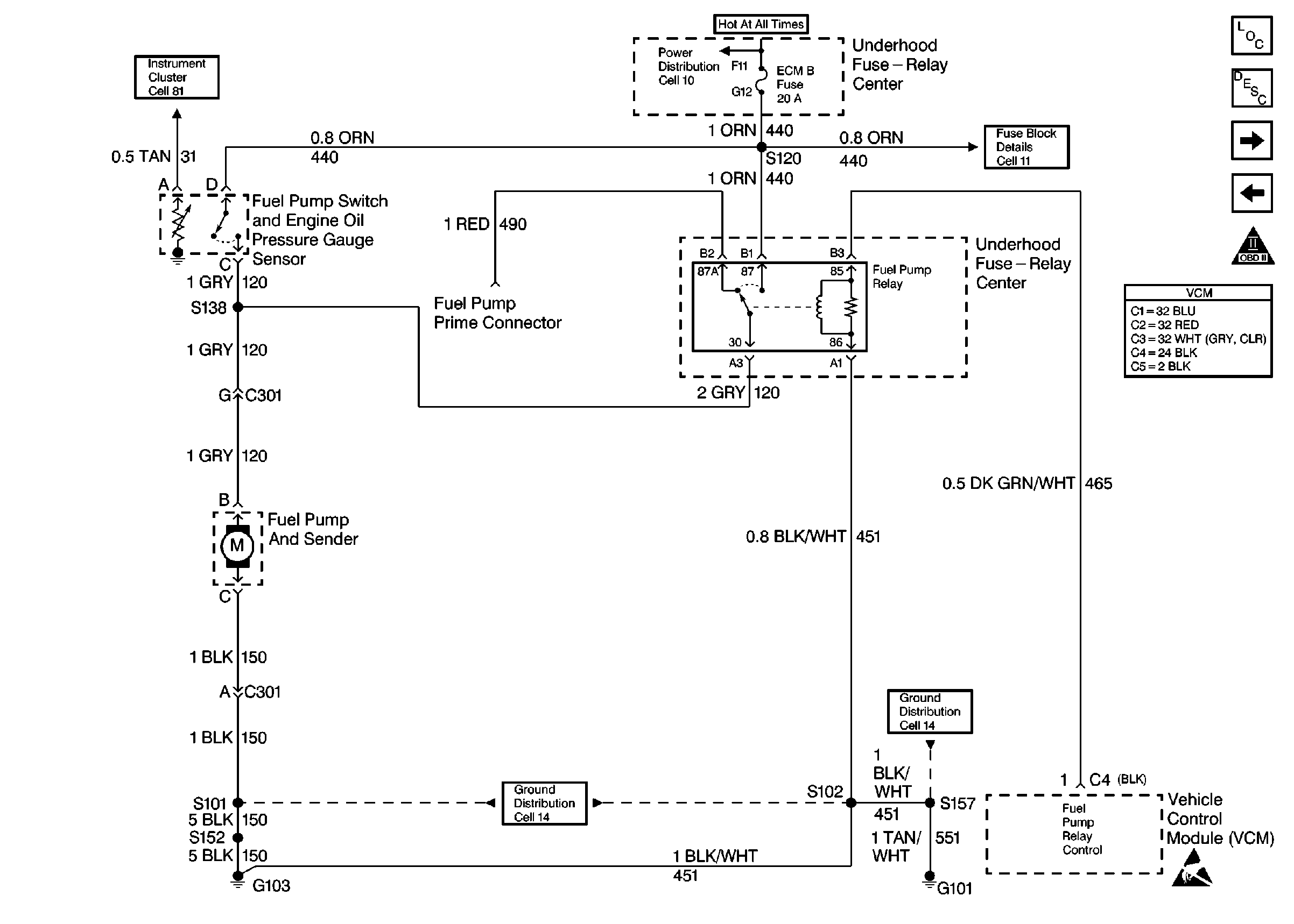
Circuit Description
When the ignition switch is turned ON, the VCM energizes the fuel pump relay which powers the in-tank fuel pump ON. The in-tank fuel pump remains ON as long as the engine is cranking or running and the VCM is receiving the distributor reference pulses. If there are no reference pulses, the VCM shuts the fuel pump OFF within 2 seconds after the ignition was turned ON or if the engine stops. The VCM will also turn ON the fuel pump for 2 seconds when the ignition is turned to the OFF position.
Should the fuel pump relay or the 12 volt relay drive from the VCM fail, the fuel pump receives a supply current through the oil pressure switch backup circuit.
Diagnostic Aids
An inoperative fuel pump relay can result in long cranking times. The time necessary for the oil pressure to reach the pressure required in order to close the oil pressure switch and supply the necessary current for the fuel pump causes the extended crank period. If the fuel pump relay circuit checks out OK, refer to Fuel System Diagnosis .
Excessive fuel may also cause long cranking times which is accompanied by the following conditions:
- A start that is not as fast as normal
- A puff of black smoke at the tailpipe
An improperly connected or faulty EVAP canister control valve can cause this problem. Disconnect the EVAP purge hose from the EVAP canister control valve in order to diagnose. Refer to Evaporative Emission Control System Diagnosis .
One or more leaking poppet nozzles may also extend the cranking time. Perform the Poppet Nozzle Test, in the Injector Balance Test Table. Refer to Fuel Injector Balance Test .
Test Description
The numbers below refer to the step numbers on the diagnostic table.
-
This step checks for the correct operation of the fuel pump system. When the ignition is turned ON, the fuel pump should operate for about 2 seconds and then turn OFF. if no ignition reference pulses are detected by the VCM.
-
This step checks the operation of the fuel pump by applying a fused 12 volts directly to the fuel pump. At this point, the problem is isolated as a pump or a control circuit problem.
-
This step will determine if the VCM is able to control the fuel pump relay.
-
This step will detect a problem in the Fuel Pump Relay control circuit.
-
This step checks for battery voltage to the Fuel Pump Relay. No voltage could be the result of an open battery circuit or a blown VCM B fuse. If the VCM B fuse is blown, the scan tool may not communicate with the vehicle.
-
The oil pressure switch serves as a backup for the fuel pump relay in order to help prevent a No Start situation. If the fuel pump relay was found to be inoperative, test the oil pressure switch circuit in order to determine why the switch did not operate the fuel pump.
Step | Action | Value(s) | Yes | No |
|---|---|---|---|---|
1 |
Important: Before clearing DTCs, use the scan tool in order to record freeze frame and the failure records for reference because the Clear Info function will lose the data. Was the Powertrain On-Board Diagnostic (OBD) System Check performed? | -- | Go to A Powertrain On Board Diagnostic (OBD) System Check | |
Does the fuel pump operate for 2 seconds? | -- | |||
Apply a 12 volt fused jumper to the fuel pump test terminal. Does the fuel pump operate? | -- | |||
Does the fuel pump operate? | -- | Go to Intermittents in Diagnostic Aids | ||
Is the test light ON? | -- | |||
6 | Connect a test light between the fuel pump relay battery feed circuit harness connector and a ground. Is the test lamp on? | -- | ||
Connect a test lamp between the fuel pump relay battery feed circuit harness terminal and the fuel pump relay ground circuit harness terminal. Is the test lamp on? | -- | |||
Replace the Fuel Pump Relay. Refer toFuel Pump Relay Replacement Important: If the original complaint was engine cranks but will not run, go to step 9. Is action complete? | -- | |||
9 |
Does the engine continue to run? | -- | ||
10 |
Is the resistance within the specified value? | 0ohms | ||
11 |
Is the test light ON? | -- | ||
12 | Probe the fuel pump feed circuit with a test lamp to the fuel pump ground terminal (vehicle side) of the chassis harness fuel pump connector. Is the test light ON? | -- | ||
13 |
Was a problem found? | -- | ||
14 | Repair the open in the battery feed circuit to the fuel pump relay harness connector terminal. Refer to Wiring Repairs in Engine Electrical. Is the action complete? | -- | -- | |
15 | Repair the open in the fuel pump relay ground circuit. Refer to Wiring Repairs in Engine Electrical. Is the action compete? | -- | -- | |
16 | Check the fuel pump/oil pressure switch harness connector terminals for a faulty connection. Was a problem found? | -- | ||
17 | Replace the fuel pump oil pressure switch. Refer to Fuel Pump Oil Pressure Switch (4.3L, 5.0L, 5.7L) Is the action complete? | -- | -- | |
18 | Replace the fuel pump. Refer to Fuel Sender Assembly Replacement (2nd design) . Is the action complete? | -- | -- | |
19 | Repair the open in the fuel pump feed circuit. Refer to Wiring Repairs in Engine Electrical. Is action complete? | -- | -- | |
20 | Repair the open in the fuel pump harness ground circuit. Refer to Wiring Repairs in Engine Electrical. Is the action complete? | -- | -- | |
21 | Repair the open in the fuel pump ground circuit. Refer to Wiring Repairs in Engine Electrical. Is the action complete? | -- | -- | |
22 | Repair the connection as necessary. Refer to Wiring Repairs in Engine Electrical. Is the action complete? | -- | -- | |
23 | Replace the VCM. Important: If the VCM is faulty, program the new VCM. Refer to VCM Replacement/Programming (With KS Calibration PROM) . Is the action complete? | -- | -- | |
24 | Repair the open or short to ground in the fuel pump relay control circuit. Is action complete? | -- | -- | |
25 |
Does the engine start and continue to run? | -- | ||
26 |
Are any DTCs displayed? | -- | Go to The Applicable DTC Table | |
27 | Using the scan tool, select the Capture Info and the Review Info. Are any DTCs displayed that have not been diagnosed? | -- | Go to The Applicable DTC Table | System OK |
