For 1990-2009 cars only
Inspection Procedure
Perform the following before disassembling the axle:
- Remove the drain plug from the axle.
- Drain the axle lubricant.
- Inspect the oil and the case for metal chips.
- Measure the rotating torque of the drive pinion and differential case assembly using an inch-pound torque wrench. Record the measurement.
- Check the ring gear backlash. Refer to Backlash Inspection and Adjustment .
Determine the source of the metal chips, such as a broken gear or bearing cage.
This information can be used in order to determine the cause of the axle problem. The information will also help when setting up and preloading the differential case.
Determine the cause of the axle problem before disassembly, if possible.
Disassembly Procedure
Tools Required
| • | J 21551 Output Shaft Bearing Remover |
| • | J 22912-B Pinion Bearing Remover |
| • | J 23907 Slide Hammer |
| • | J 29369-1 Bushing/Bearing Remover |
| • | J 33791 Bushing Remover and Installer Set |
| • | J 33792 Side Bearing Adjuster Socket |
| • | J 33837 Pinion Bearing Cup Remover and Installer |
| • | J 36611 Output Shaft Bearing Remover |
| • | J 42213 Side Bearing Adjuster Socket |
| • | J 8092 Driver Handle |
| • | J 8614-01 Pinion Flange Holder |
- Remove the left inner axle shaft.
- Remove the inner axle shaft seal cover and the seal.
- Remove the inner axle shaft seal by doing the following:
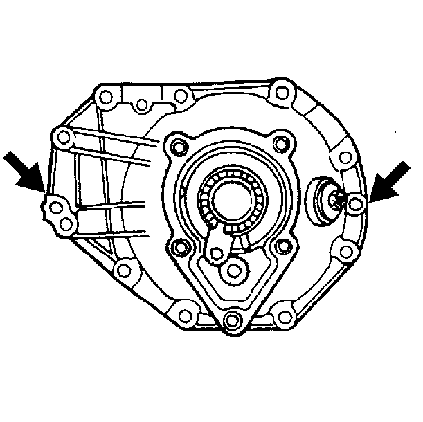
- Remove the differential carrier assembly bolts.
- Separate the left carrier case half from the right carrier case half by inserting a screwdriver into the slots provided and prying the case apart.
- Remove the differential case assembly.
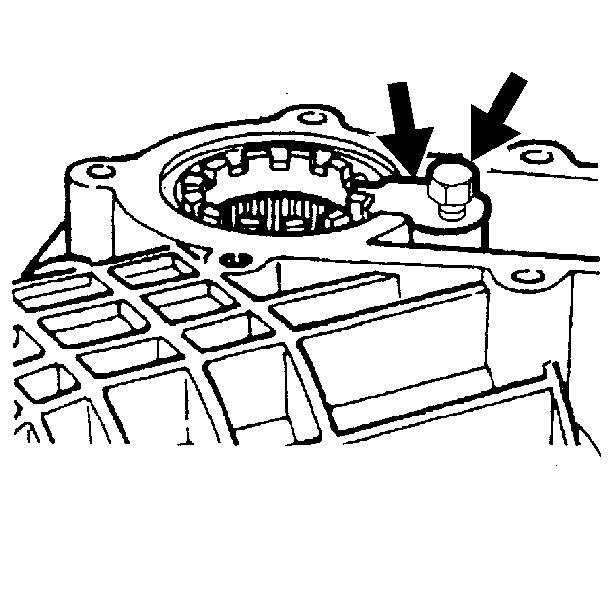
- Remove the differential bearing adjuster nut lock bolts and the differential bearing adjuster nut locks.
- Remove the left differential bearing adjuster and the differential case bearing cup by doing the following:
- Remove the right differential bearing adjuster and the differential case bearing cup by doing the following:
- Remove the left inner axle shaft bearing using the J 36611 (2) and the J 8092 (1).
- Remove the right inner shaft bearing using the J 21551 (2) and the J 8092 (1).
- Install the J 8614-01 as shown.
- Remove the washer.
- Install the J 8614-2 (2) and the J8614-3 (3) into the J 8614-01 (1) as shown.
- Remove the pinion flange by turning the J 8614-3 (3) clockwise while holding the J 8614-01 (1).
- Remove the dust deflector from the pinion flange by doing the following:
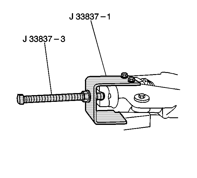
- Mount the left side differential carrier case in the J 33837 -1.
- Install the J 33837-3.
- While holding the J 33837-3 , turn the nut sleeve of the J 33837 -3 counterclockwise to remove the following components:
- Remove the collapsible spacer from the pinion.
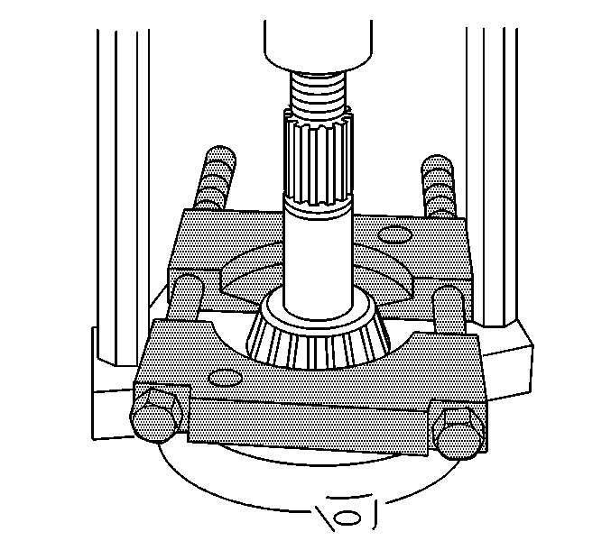
- Remove the inner pinion bearing by installing the J 22912-B between the pinion bearing and the pinion gear and pressing the bearing off the pinion.
- Remove the pinion gear selectable shim.
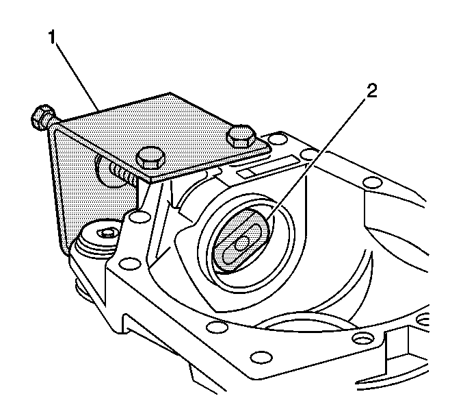
- Install the J 33837-6 (2) onto the J 33837-3 between the inner and the outer pinion bearing cup.
- While holding the J 33837-3, turn the nut sleeve of the J 33837-1 clockwise in order to remove the following components:
- Install the J 33837-6 (2) onto the J 33837-3 on the inside surface of the outer bearing cup.
- While holding the J 33837-3, turn the nut sleeve of the J 33837-1 counterclockwise in order to press the inner pinion bearing cup out from the differential carrier case.
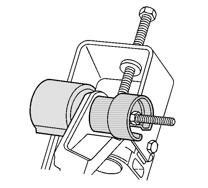
- Install the J 33791 onto the differential carrier assembly bushings.
- Remove the bushings using the J 33791 .
| 3.1. | Install the inner axle shaft seal cover in a vise. |
| 3.2. | Install the J 29369-1 to the backside of the inner axle shaft seal. |
| 3.4. | Remove the inner axle shaft seal by pulling on the J 23907 . |
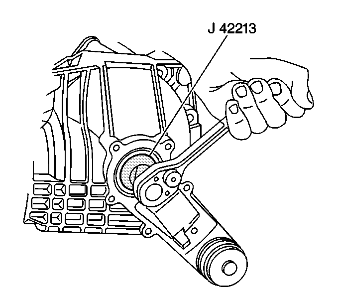
| 8.1. | Install the J 42213 onto the differential bearing adjuster nut. |
| 8.2. | Turn the J 42213 clockwise in order to remove the differential bearing adjuster and the differential case bearing cup out of the bore. |
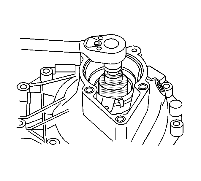
| 9.1. | Install the J 33792 onto the differential bearing adjuster nut. |
| 9.2. | Turn the J 33792 clockwise in order to remove the differential bearing adjuster and the differential case bearing cup out of the bore. |
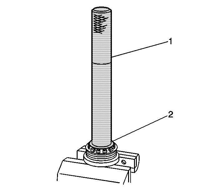
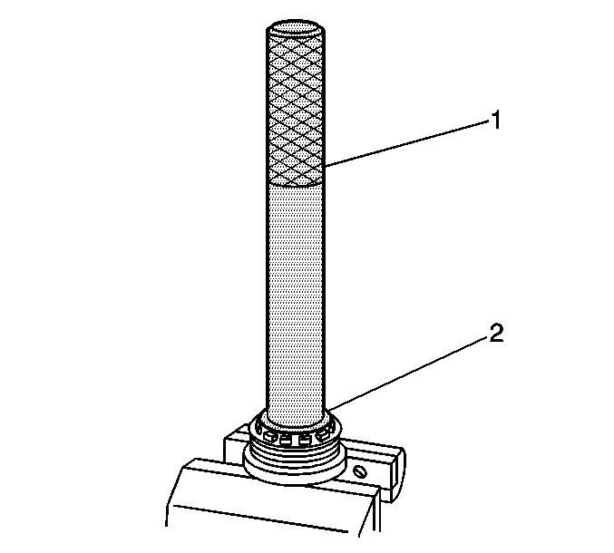
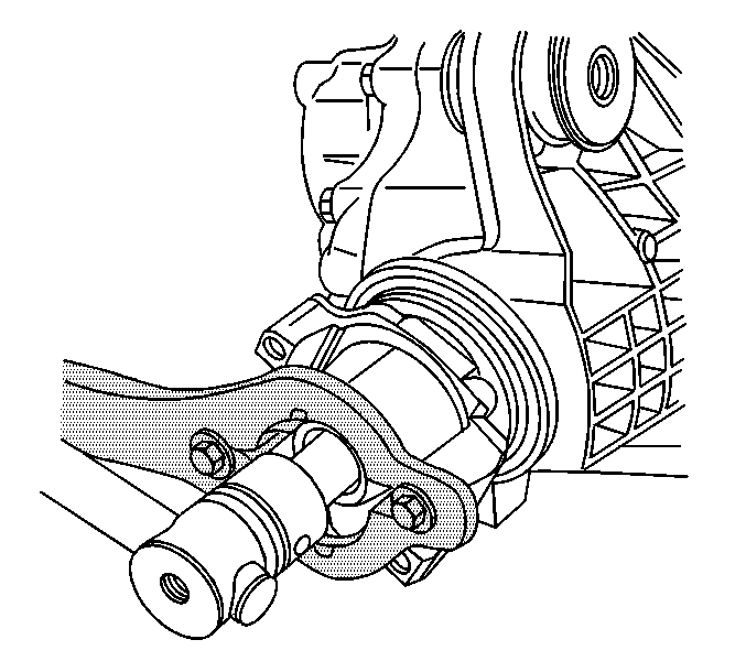
Remove the pinion nut while holding the J 8614-01 .
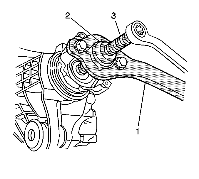
| 16.1. | Tap the deflector off the pinion flange. |
| 16.2. | Clean up the stake points on the pinion flange. |
| • | The drive pinion |
| • | The drive pinion selectable shim |
| • | The inner pinion bearing |
| • | The collapsible spacer |
| • | The pinion oil seal |
| • | The pinion outer bearing |
| • | The pinion outer bearing cup |
