For 1990-2009 cars only
Removal Procedure
- Disable the SIR system. Refer to Disabling the SIR System in SIR.
- Remove the steering column trim covers from the steering column. Refer to Steering Column Trim Covers Replacement - On Vehicle .
- Disconnect the steering column electrical connectors.
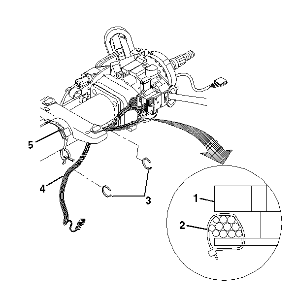
- Remove the steering column wiring harness tie straps.
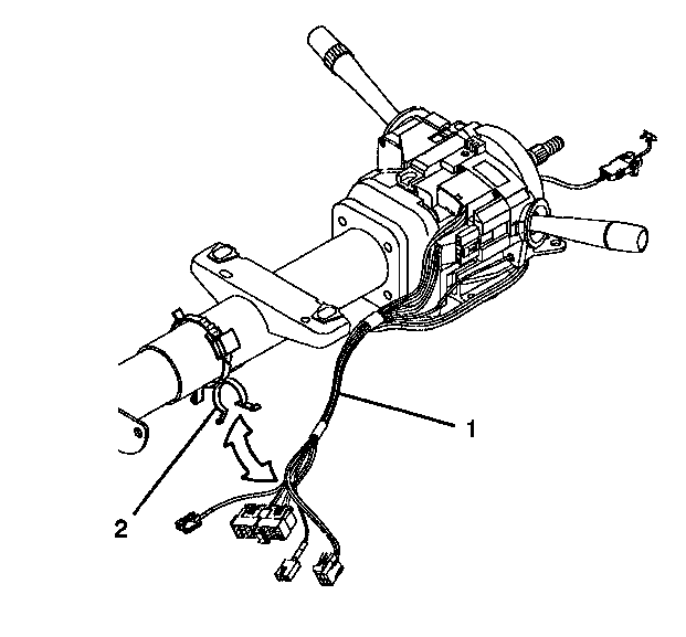
- Remove the steering column wire harness (1) from the steering column and the wire harness strap (2).
- Remove and dispose of the small wire harness straps from the wire harness assembly (1).
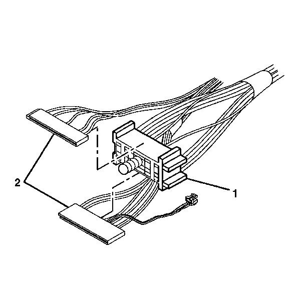
- Disconnect the multifunction switch electrical connectors (2) from the bulkhead connector (1).
- Remove the key alarm connector (1) from the lock module assembly (2) in the following way:
- Slide the ignition and key alarm switch assembly (2) out of the lock module assembly (1).
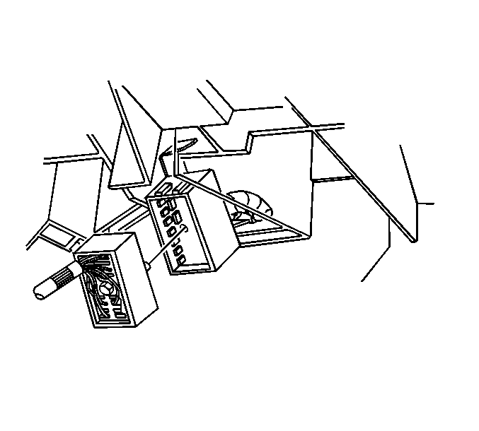
Caution: This vehicle is equipped with a Supplemental Inflatable Restraint (SIR) System. Failure to follow the correct procedure could cause the following conditions:
• Air bag deployment • Personal injury
In order to avoid the above conditions, observe the following guidelines:
• Unnecessary SIR system repairs • Refer to SIR Component Views in order to determine if you are performing service on or near the SIR components or the SIR wiring. • If you are performing service on or near the SIR components or the SIR wiring, disable the SIR system. Refer to Disabling the SIR System.
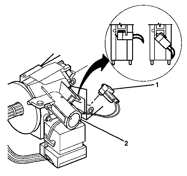
| 8.1. | Rotate the key alarm connector (1) 90 degrees. |
| 8.2. | Pull the key alarm connector (1) out of the lock module assembly (2). |
| 8.3. | Remove the passkey connector from the lock module assembly (2). |
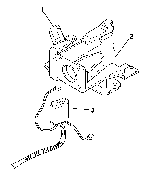
Installation Procedure
- Slide the ignition and key alarm switch assembly (2) into the lock module assembly (1).
- Install the key alarm connector (1) into the lock module assembly (2).
- Connect the multifunction switch electrical connectors to the bulkhead connector (1).
- Install the wire harness assembly (1) to the wire harness strap (2).
- Attach new wire harness straps to the wire harness assembly (1).
- Connect the steering column electrical connectors to the vehicle.
- Install the trim covers to the column. Refer to Steering Column Trim Covers Replacement - On Vehicle .
- Enable the SIR system. Refer to Enabling the SIR System in SIR.


| 2.1. | Push the key alarm connector (1) into the lock module assembly (2). |
| 2.2. | Rotate the key alarm connector (1) 90 degrees so that the key alarm connector (1) locks into place. |
| 2.3. | Install the passkey connector into the lock module assembly (2). |


