SERVICE MANUAL UPDATE-SEC. 7B1 MANUAL TRANS. UNIT REPAIR

SUBJECT: SERVICE MANUAL UPDATE - SECTION 7B1 - NEW VENTURE GEAR 5LM60 MANUAL TRANSMISSION UNIT REPAIR (REVISED INFO)
VEHICLES AFFECTED: 1993 S/T, C/K MODELS
This information replaces the information found under NEW VENTURE GEAR 5LM60 MANUAL TRANSMISSION UNIT REPAIR in SECTION 7B1 of the 1993 Light Duty Truck Unit Repair Manual.
Beginning with the 1993 model year, the New Venture Gear 5LM60 Transmissions were built with a single shift shaft. Due to the design change, the transmission is now called the New Venture Gear 3500 Manual Transmission.
Update your 1993 Light Duty Truck Unit Repair Manual with the following pages.
SECTION 7B1
NEW VENTURE GEAR 3500 MANUAL TRANSMISSION
NOTICE: When fasteners are removed, always reinstall them at the same location from which they were removed. If a fastener needs to be replaced, use the correct part number fastener for that application. If the correct part number fastener is not available, a fastener of equal size and strength (or stronger) may be used. Fasteners that are not reused, and those requiring thread locking compound will be called out. The correct torque value must be used when installing fasteners that require it. If the above conditions are not followed, parts or system damage could result.
CONTENTS
SUBJECT PAGE ------- ---- General Description 7B1- 1 General Service Information 7B1- 1 Disassembly 7B1- 2 Transmission Disassembly 7B1- 2 Mainshaft Disassembly 7B1- 8 Synchronizer Disassembly 7B1- 10 Reverse Idler Gear Disassembly 7B1- 10 Front Housing Disassembly 7B1- 10 Rear Housing Disassembly 7B1- 15 Cleaning and Inspection 7B1- 16 Mainshaft and Synchronizers 7B1- 16 Countershaft 7B1- 17 Reverse Idler Gear 7B1- 17 Front and Rear Housings 7B1- 17 Shift Shaft/Rail and Fork assembiles 7B1- 18 Shift Lever Housing 7B1- 18 Assembly 7B1- 19 Input Shaft Bearing Retainer Assembly 7B1- 19 Rear Housing Assembly 7B1- 20 Front Housing Assembly 7B1- 20 Reverse Idler Gear Assembly 7B1- 21 Synchronizer Assembly 7B1- 21 Mainshaft Assembly 7B1- 21 Transmission Assembly 7B1- 25 Specifications 7B1- 29 Fastener Tightening Specifications 7B1- 29 Lubrication Specifications 7B1- 29 Special Tools 7B1- 30
GENERAL DESCRIPTION
The New Venture Gear 3500 transmission is a 5-speed unit that is synchronized in all forward gears.
The transmission has a two-piece aluminum housing containing the front input shaft, rear output shaft, mainshaft gears, countershaft, reverse idler gear, shift forks, and shift shaft components.
Two different versions of the 3500 transmission are used and can be identified by the RPO code or the model of truck from which it was removed. The MG5 transmission is used in the C/K truck line and MY2 version is used in S/T vehicles.
GENERAL SERVICE INFORMATION
Lubricant
o The lubricant may appear to be very dark in color.
o This is a normal condition.
Cleaning
o Thoroughly clean the exterior of the transmission.
DISASSEMBLY
TRANSMISSION DISASSEMBLY
Disassemble (Figures 1 through 15)
Tool Required:
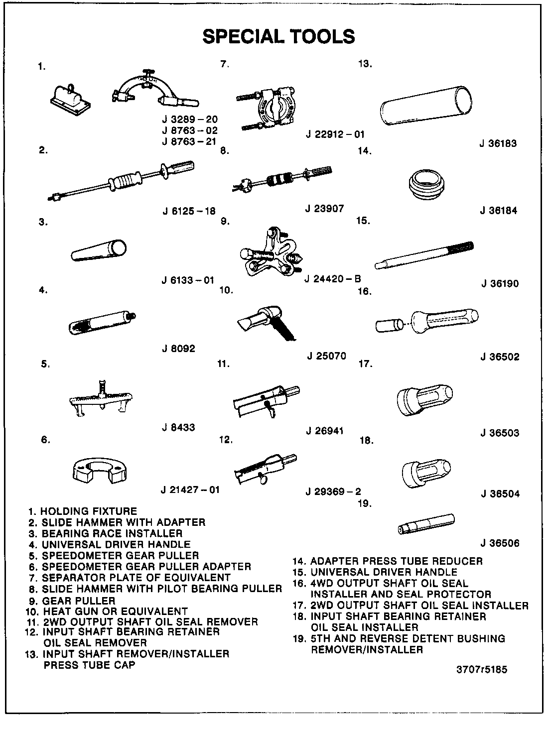
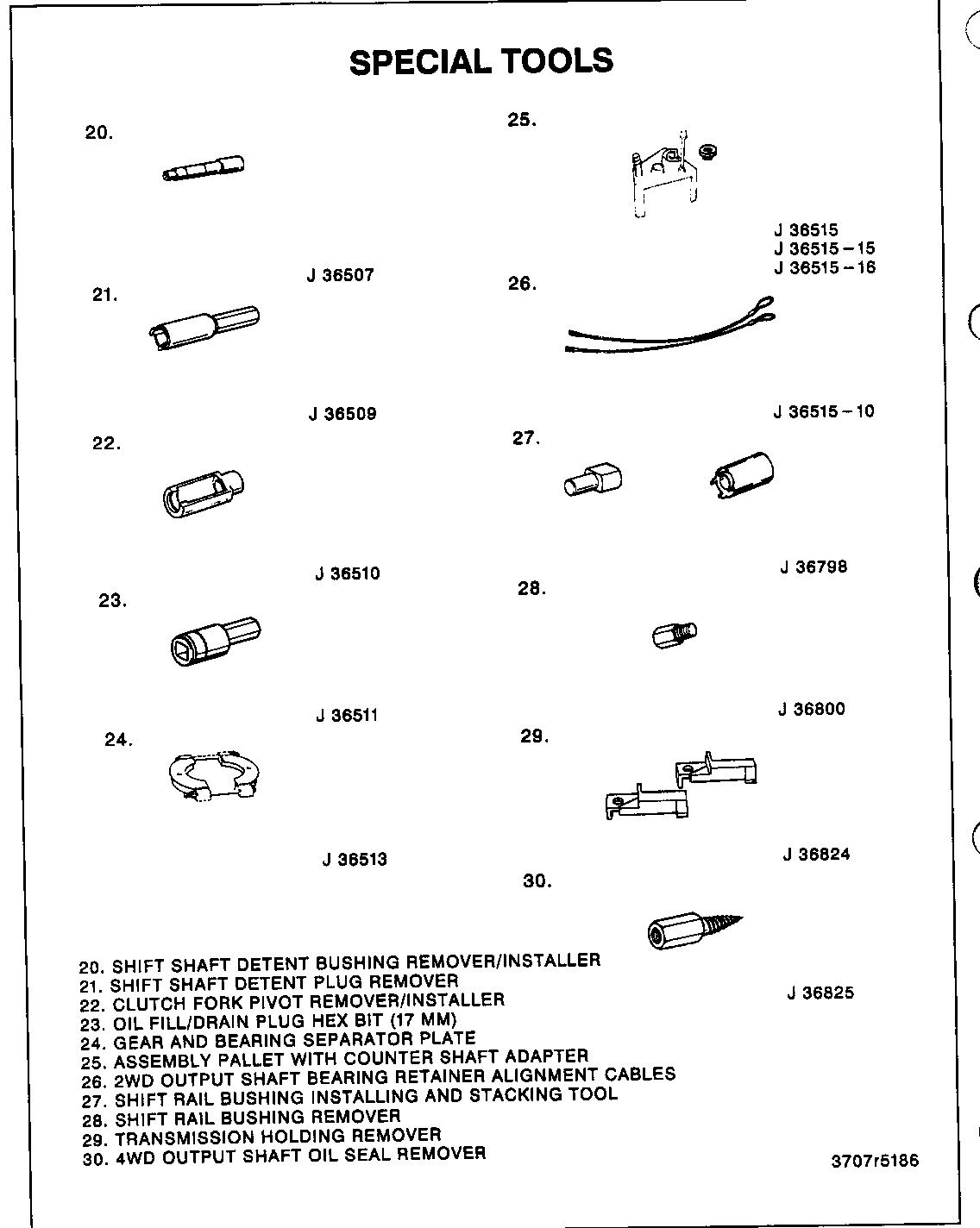
J 3289-20 Base Holding Fixture J 8763-02 Holding Fixture C-Clamp J 8763-21 Balance Bracket for C-Clamp J 36824 Transmission Adapters J 36509 Detent Sprint Plug Remover J 23907 Slide Hammer J 36825 4WD Output Shaft Oil Seal Remover (4WD models only) J 36515 Assembly Pallet J 36515-15 Mainshaft Adapter J 36515-16 Countershaft Adapter J 24420-B Gear Puller (2WD models only) J 21427-01 Speedometer Gear Puller Adapter (2WD models only) J 26941 Output Shaft Oil Seal Remover (2WD only)
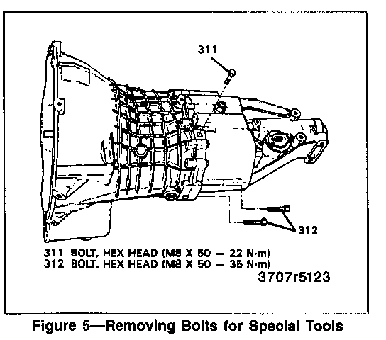
1. Idler shaft support bolt (311) and bottom two bolts (312) (figure 5).
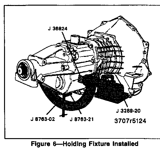
o J 8763-21 onto J 8763-02 (figure 6).
o J 36824 onto the transmission case.
o J 8763-02 onto J 36824.
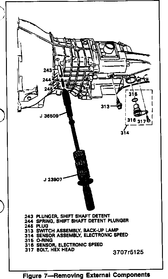
2. Backup lamp switch assembly (313) (figure 7).
3. Shift shaft block-out bushing pin (236).
4. Bolt (317) and electronic speed sensor assembly (314) (2WD models only).
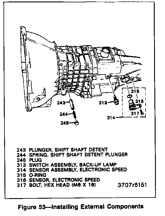
5. Detent plug (245) using J 36509 and J 23907, spring (244), and plunger (243) (figure 7).
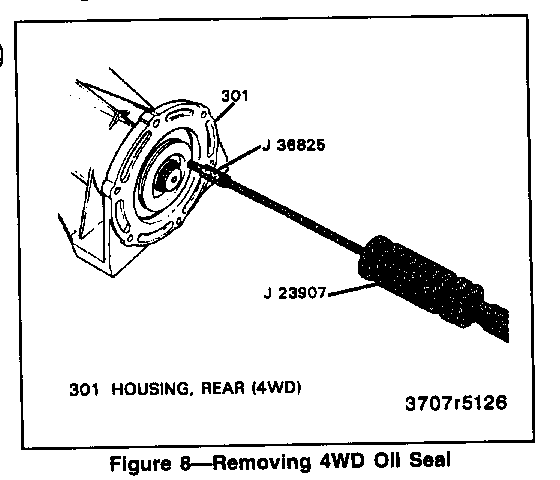
6. Output shaft oil seal (320) using J 36825 and J 23907 (figure 8) (4WD models only).
o Use J 36825 by screwing into one of the three perforated holes in the seal (4WD models only).
7. Position transmission vertically.
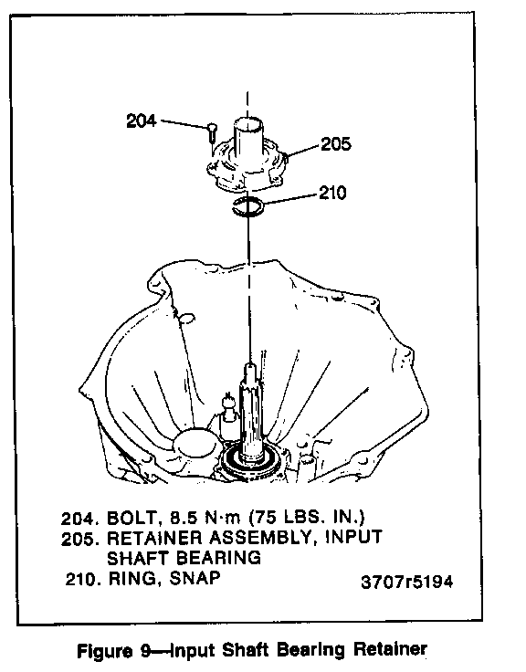
8. Six bolts (204) and input shaft bearing retainer assembly (205) (figure 9).
A. Tap clutch release bearing pilot with a rubber mallet.
B. Save the input bearing retainer washer.
9. Snap ring (210) and shim (212).
10. Position transmission horizontally.
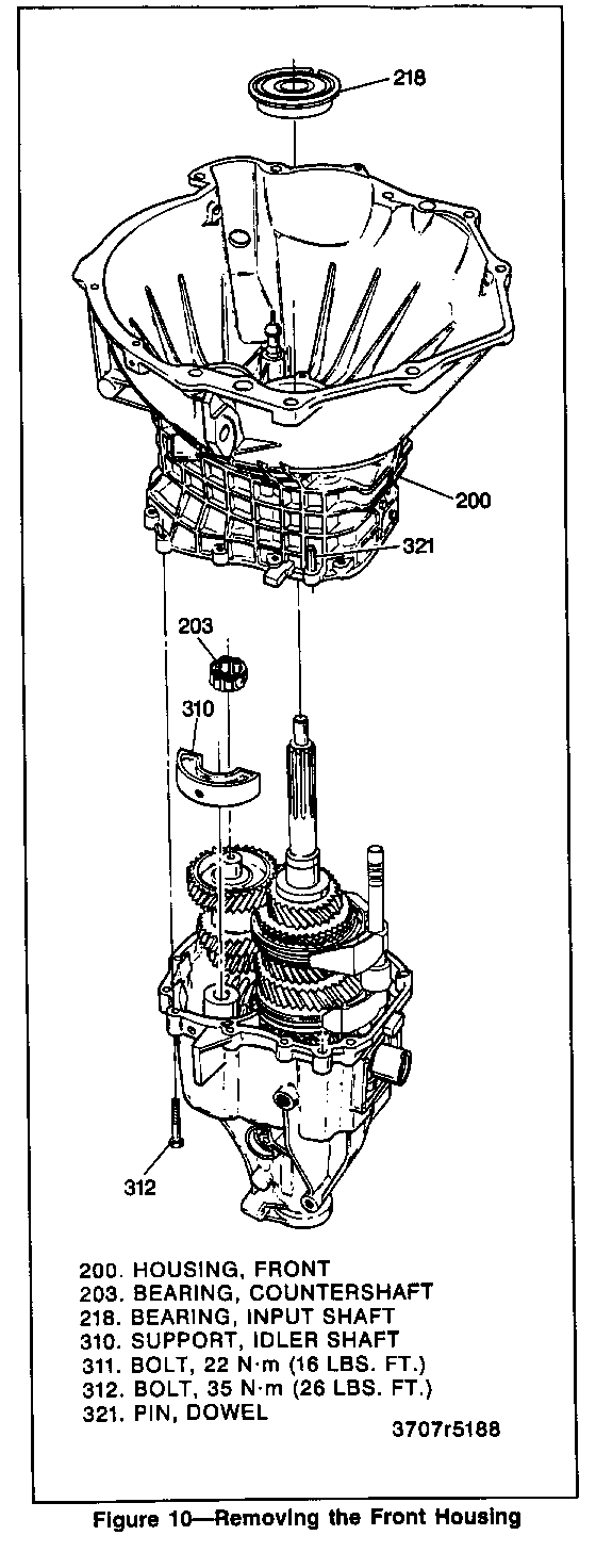
11. Front housing to rear housing bolts (312) (figure 10).
12. Drive dowels (321) into front housing.
13. Front housing (200).
14. Countershaft bearing (35).
15. Idler shaft support (310).
o Snap out.
16. Move all shift forks forward to engage fourth, second, and reverse gears.
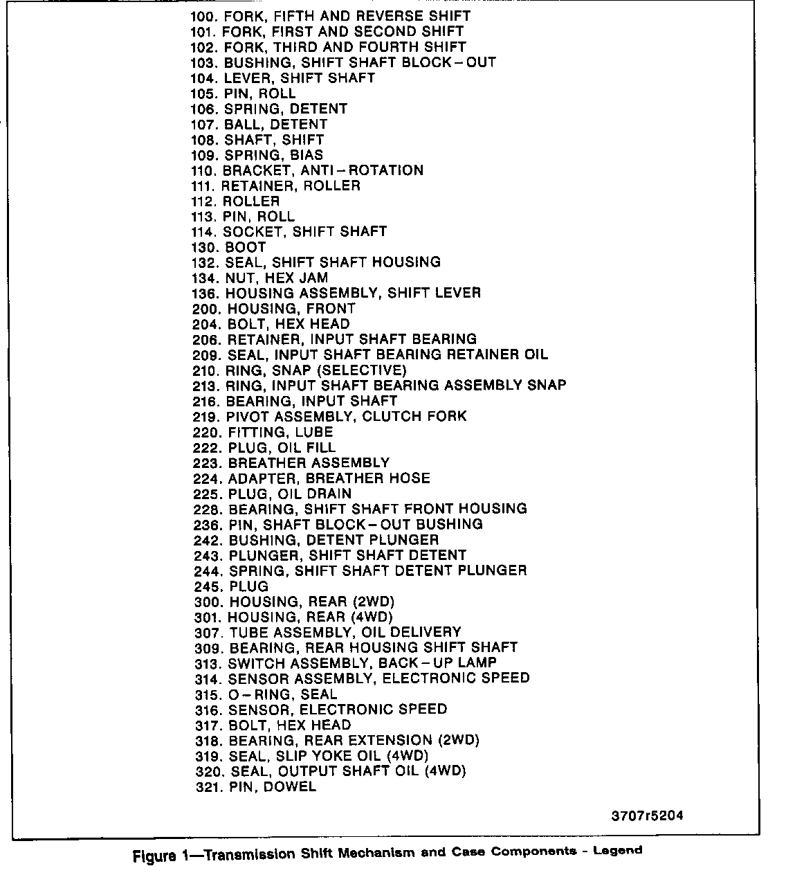
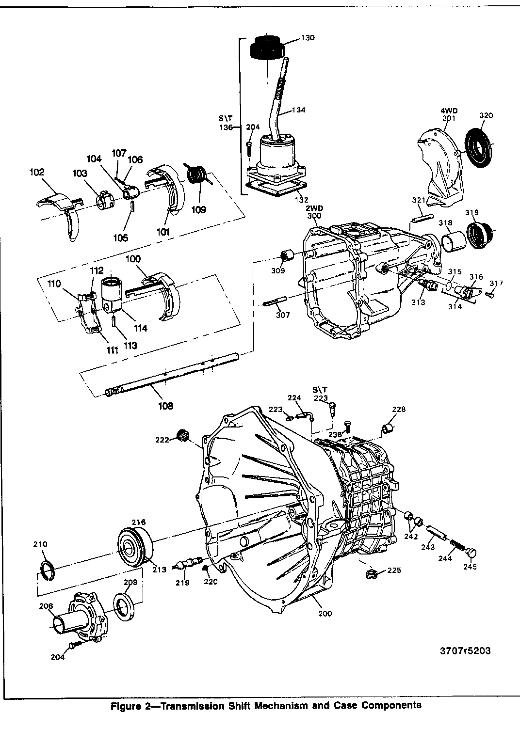
17. Roll pin (105) (figure 1).
Important
A. Support the shift shaft (108) end while driving out lever roll pin.
B. Allow roll pin to clear second gear.
C. Do not loose shift lever detent ball (106) and spring (107).
18. Place all gears in neutral. Then engage fifth gear.
19. Push shift shaft (108) all the way into the housing (300) or (301).
20. Shift shaft socket assembly roll pin (113) (figure 1).
o Rotate input shaft until gap in the fifth/reverse synchronizer hub is directly under the roll pin.
o Drive shift socket pin down using a 5-mm (3/16-inch) punch.
o Pin will fall into the case.
NOTICE: Excessive force will "peen" the shift shaft and damage the rear housing shift shaft bearing (309) causing increased shift effort.
21. Shift shaft (108), shift shaft socket assembly (114), anti-rotation bracket (112), biasing spring (109), lever (104), and shift shaft block out bushing (103).
22. Rotate third-fourth shift fork (102) counterclockwise and remove.
23. Loosen, but do not remove, 3 bolts (304) on the rear of case (2WD only).
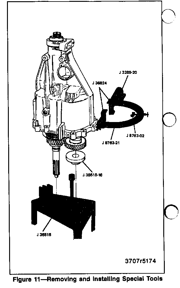
24. Install J 36515-15 and J 36515-16 onto the input and countershaft. Install J 36515 to the transmission assembly (figure 11).
25. J 8763-02 and J 36824 from the housing.
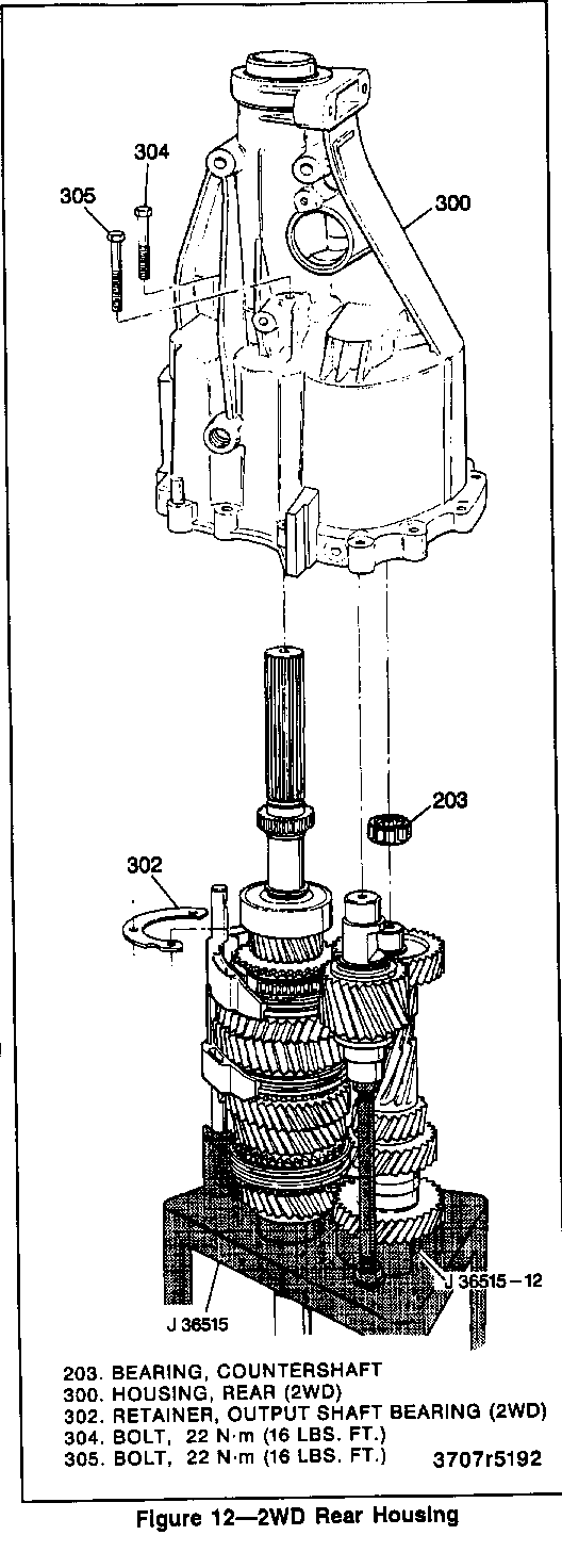
26. Bolts (304) from the rear housing (2WD only) (figure 12).
27. Output shaft bearing snap ring (43) (4WD only).
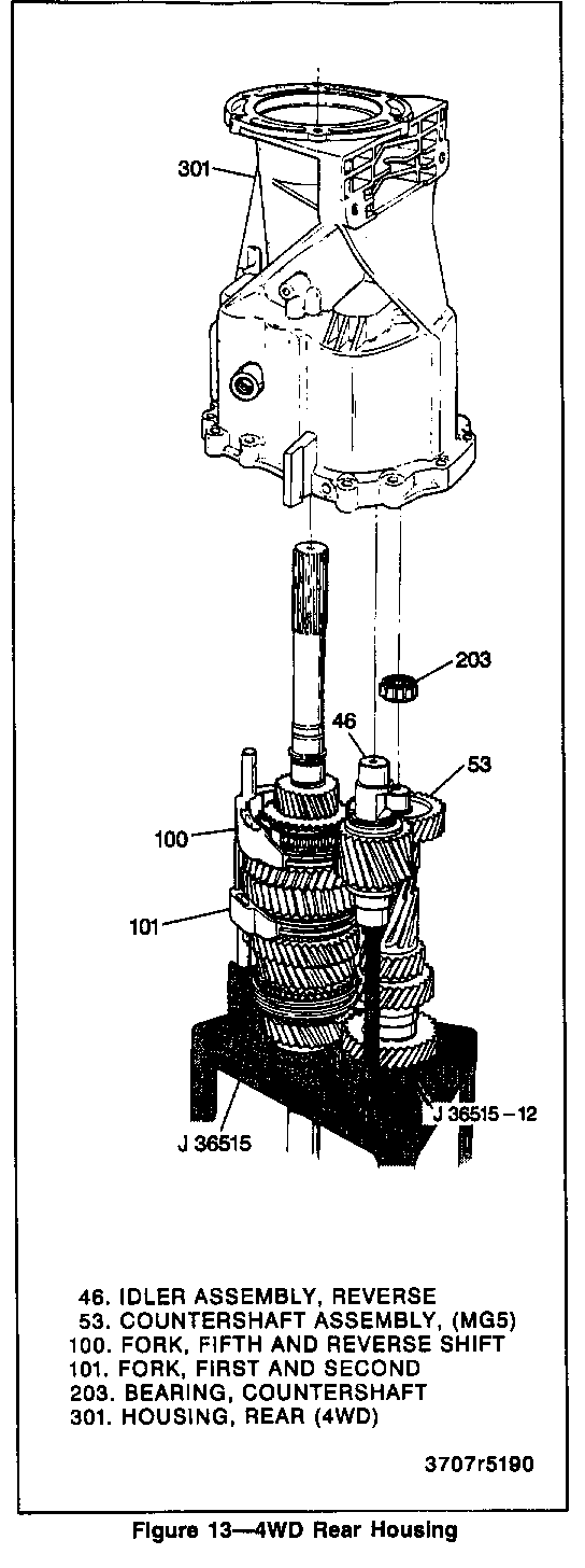
28. Tap housing with a rubber mallet and remove rear housing from assembly (figures 12 and 13).
29. Output shaft bearing retainer (302) (2WD models only) (figure 12).
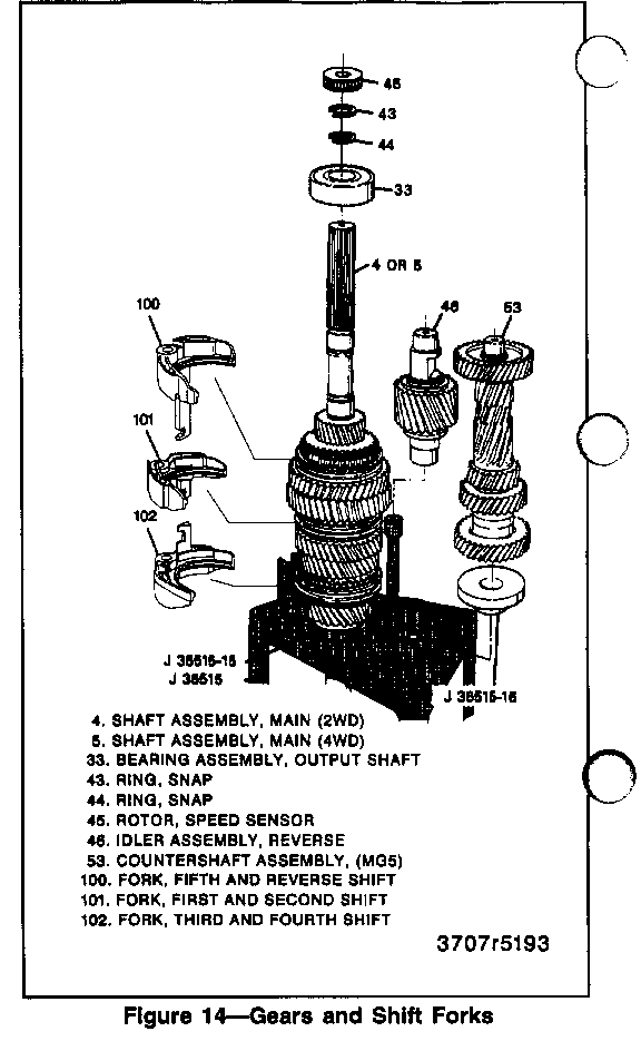
30. Shift forks (100 and 101) (figure 14).
31. Reverse idler gear (46).
32. Countershaft (53).
33. Bearing (203) (2WD models only).
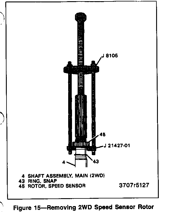
o Slide the snap ring (43) away from the rotor to make clearance for J21427-01 (figure 15).
34. Speed sensor rotor (45) using J 21427-01 and J 24420-B (2WD models only).
o Do NOT reuse rotor after removal.
35. Snap ring (43) (2WD models only).
36. Snap ring (44) (2WD models only).
37. Bearing assembly, output shaft (33) (2WD models only).
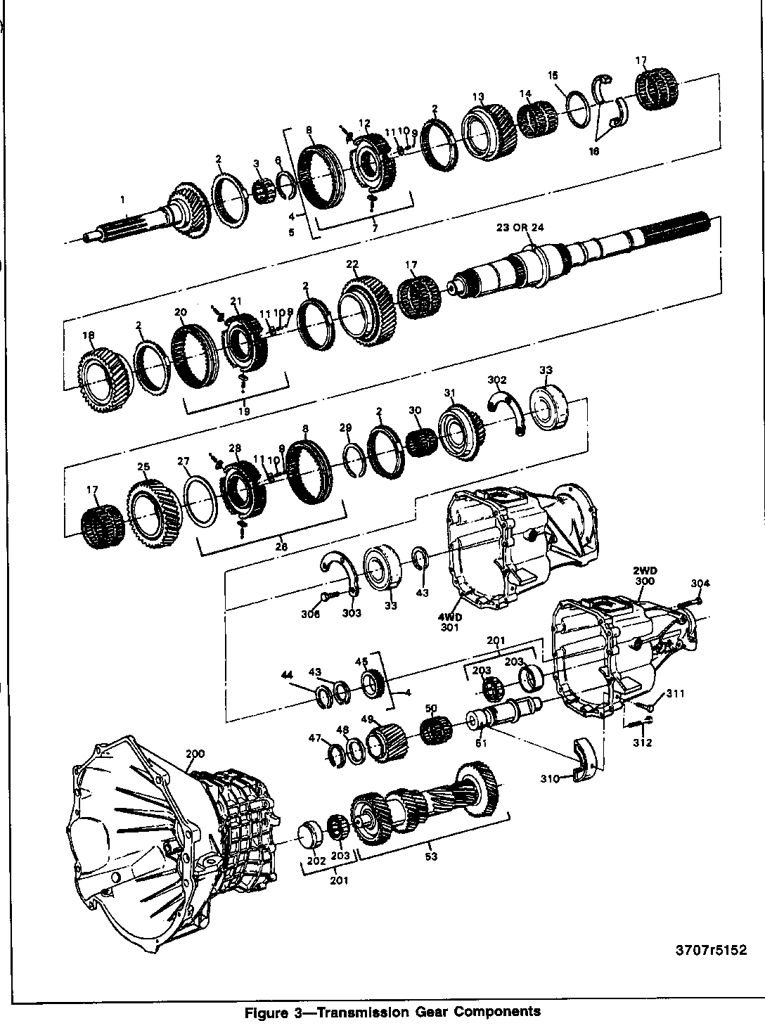
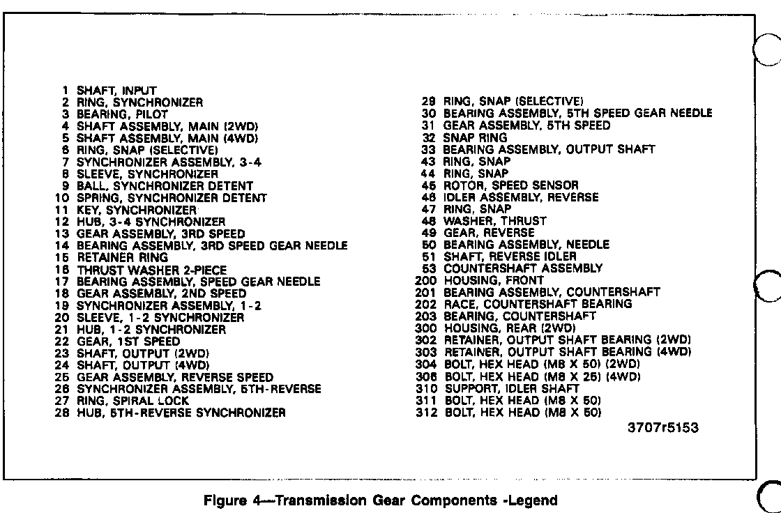
38. Mainshaft assembly (4) or (5) (figure 14).
Important
o Leave the synchronizer ring (2) on the third-fourth synchronizer assembly (7) to prevent the synchronizer detent balls (9) from popping out.
39. Input shaft gear (1) and pilot bearing (3).
MAINSHAFT DISASSEMBLY
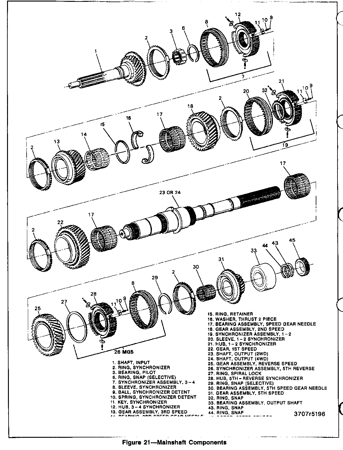
Disassemble (Figures 16 through 21)
Tools Required:
Hydraulic Press J 36513 Gear and Bearing Separator Plate
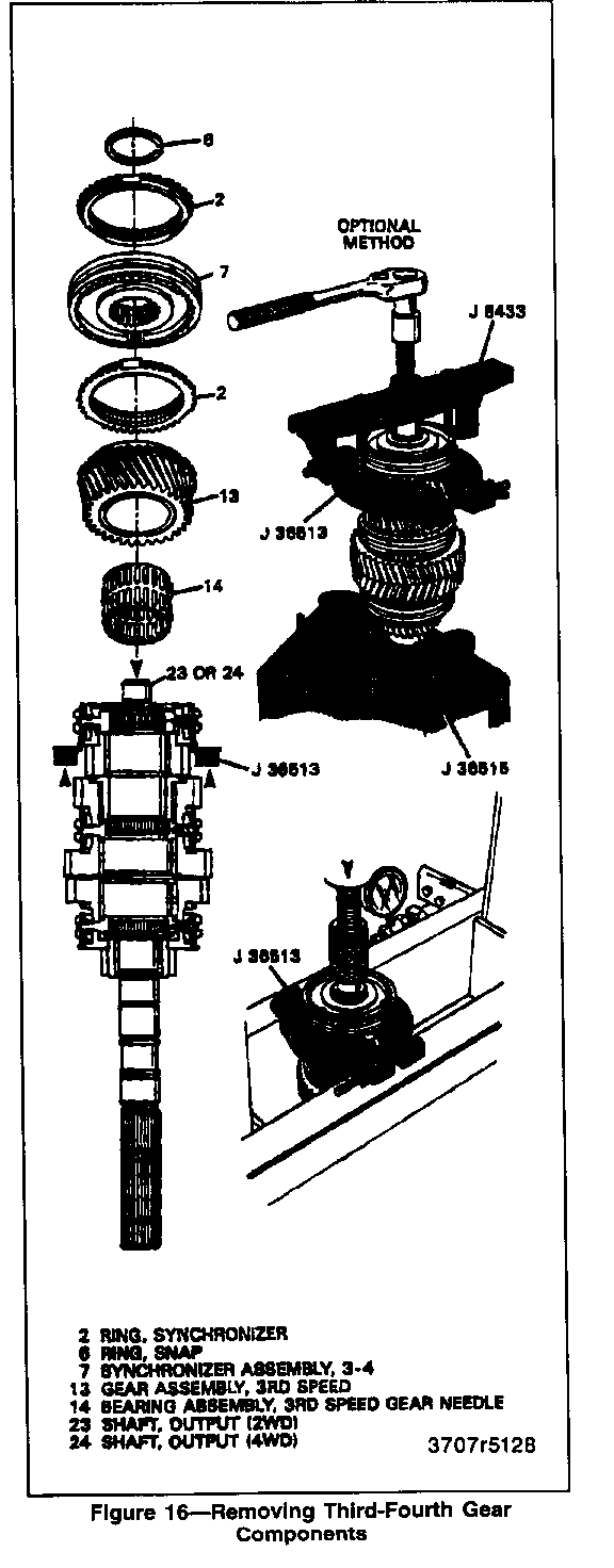
1. Snap ring (6) (figure 16).
NOTICE: Optional method in figure 16 can be used if the service press bed is not wide enough for the first speed to pass through. This, method can be used to totally disassembly the main shaft, if necessary.
2. Third-fourth synchronizer assembly (7), synchronizer rings (2), and third speed gear (13) using J 36513 and hydraulic press.
A. Scribe on hub and sleeve so the parts can be reinstalled in the same position.
B. Leave the synchronizer rings (2) to prevent the synchronizer detent balls (9) from popping out.
3. Third gear needle bearing (14).
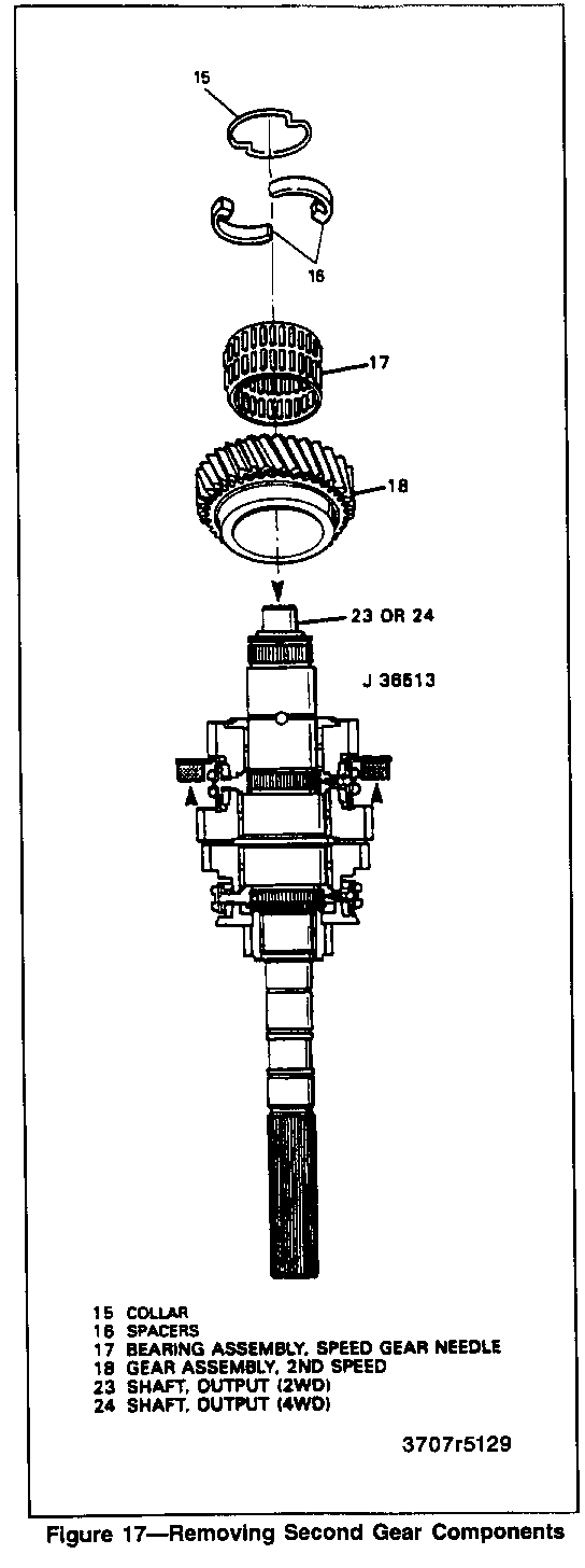
4. Collar (15) and spacers (16) (figure 17).
5. Second speed gear assembly (18).
6. Speed gear bearing assembly (17).
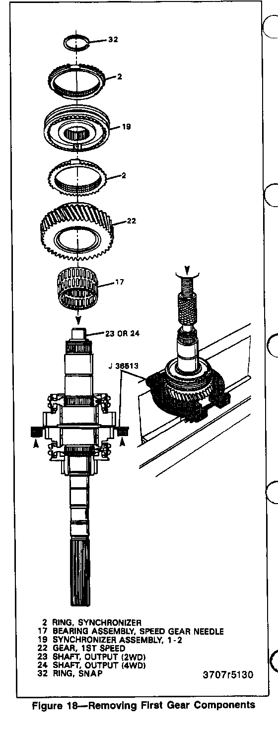
o Leave the synchronizer ring (2) on the first-second synchronizer assembly (19) to prevent the synchronizer detent balls (9) from popping out.
7. First speed gear (22) and first-second synchronizer assembly (19) using J36513 and hydraulic press (figure 18).
A. Scribe on hub and sleeve so the parts can be reinstalled in the same position.
B. Leave the syncronizer rings (2) on the first-second synchronizer assembly (19) to prevent the synchronizer detent balls (9) from popping out.
8. First speed gear needle bearing assembly (17).
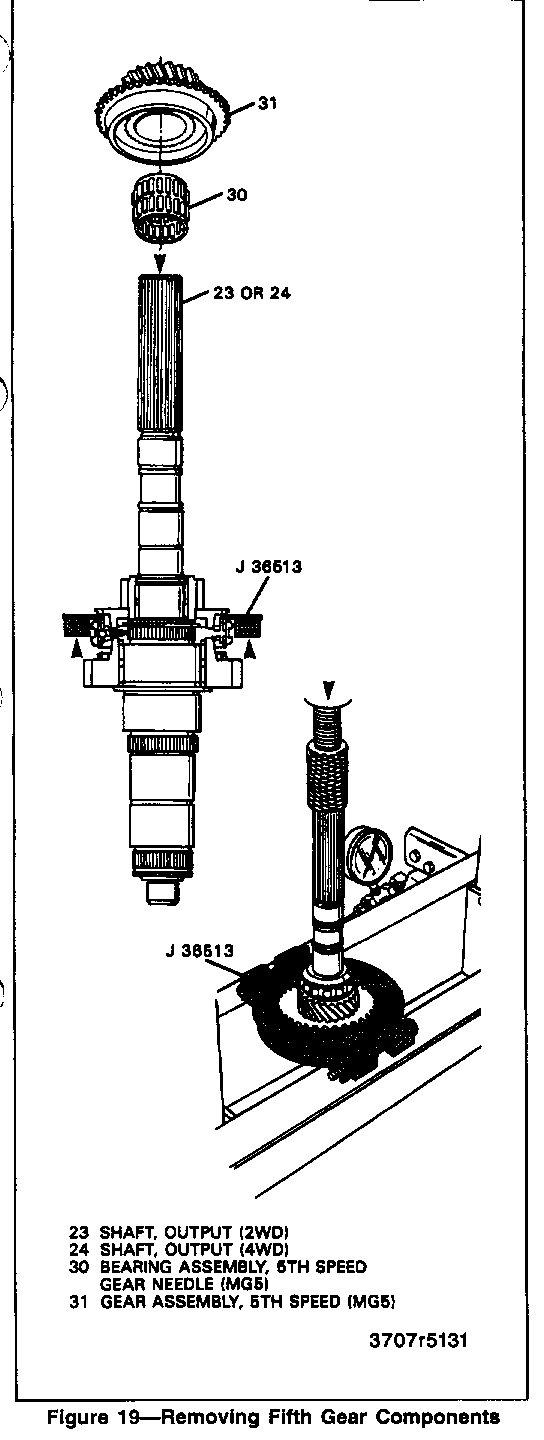
9. Fifth speed gear (31) (figure 19).
10. Fifth speed gear bearing (30).
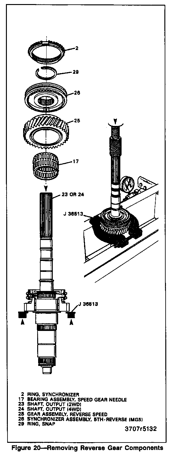
11. Snap ring (29) (figure 21).
12. Reverse speed gear assembly (25) and fifth-reverse synchronizer assembly (26) using J 36513 and hydraulic press (figure 20).
A. Scribe on hub and sleeve so the parts can be reinstalled in the same position.
B. Leave the synchronizer ring (2) on the fifth-reverse synchronizer assembly (26) to prevent the synchronizer detent balls (9) from popping out.
13. Reverse speed gear bearing assembly (17).
SYNCHRONIZER DISASSEMBLY
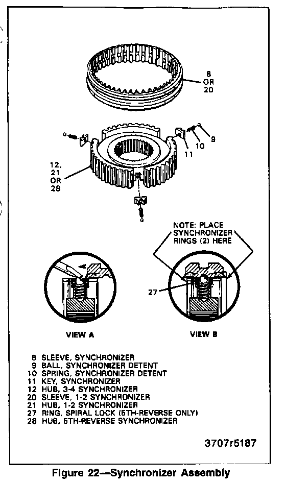
Disassemble (Figure 22)
1. Place first-second, third-fourth, and fifth speed synchronizers in separate shop towels. Wrap assemblies and press against inner hub.
Important
o Do not mix parts.
REVERSE IDLER GEAR DISASSEMBLY
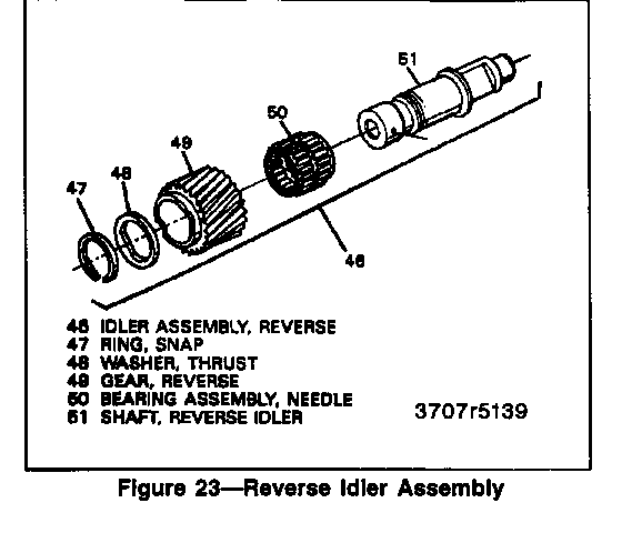
Disassemble (Figure 23)
1. Snap ring (47).
2. Thrust washer (48).
3. Reverse gear (49).
4. Bearing assembly (50).
FRONT HOUSING DISASSEMBLY
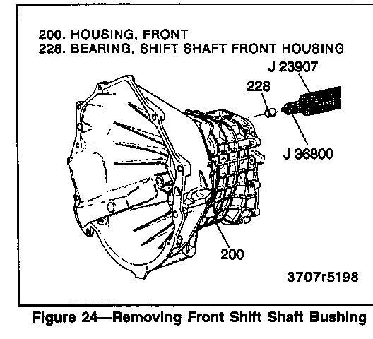
Disassemble (Figures 1, 2, 24 through 27)
Tools Required:
J 36183 Input Shaft Press Tube with Cap J 36184 Adapter Press Tube Reducer J 23907 Slide Hammer with Pilot Bearing Puller J 6125-1B Slide Hammer J 36510 Clutch Fork Pivot Remover/Installer J 36507 Detent Bushing Remover and Installer J 36800 Shift Rail Busing Remover J 36511 Oil Fill Plug Hex Bit (17 mm)
1. Press out input shaft bearing (216) using J 36183, J 36184 and hydraulic press.
2. Shift rail front housing bushing (228), using J 36800 and J 23907 (figure 24).
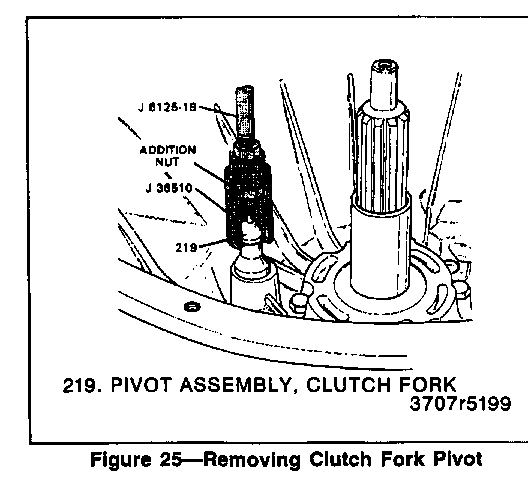
3. Clutch fork pivot assembly (219), using J 36510 and J 6125-1B (figure 25).
A. Put an additional nut (3/8-16 thread) onto J 36510 and thread J 6125-1B onto nut.
B. Tighten both nuts.
C. Slide hammer out pivot.
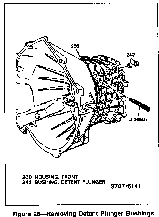
4. Two detent plunger bushings (242), if necessary, using J 36507 (figure 26).
o Remove ONE bushing at a time.
5. Breather assembly (223).
o Do NOT remove metal tube from case.
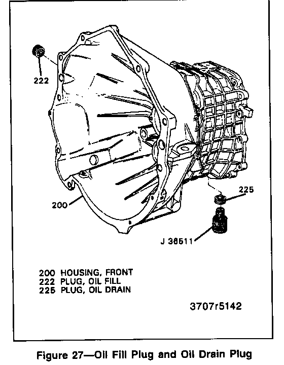
6. Oil fill plug (222) and oil drain plug (225) using J 36511 (figure 27).
7. Gasket material from the case using liquid gasket remover.
REAR HOUSING DISASSEMBLY
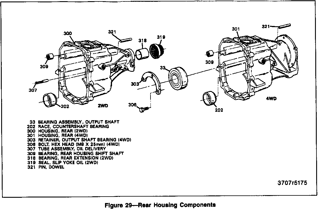
Disassemble (Figures 28, 29, and 30)
Tools Required:
Hydraulic Press J 23907 Slide Hammer with Pilot Bearing Puller J 26941 2WD Output Shaft Oil Seal Remover (2WD models only)
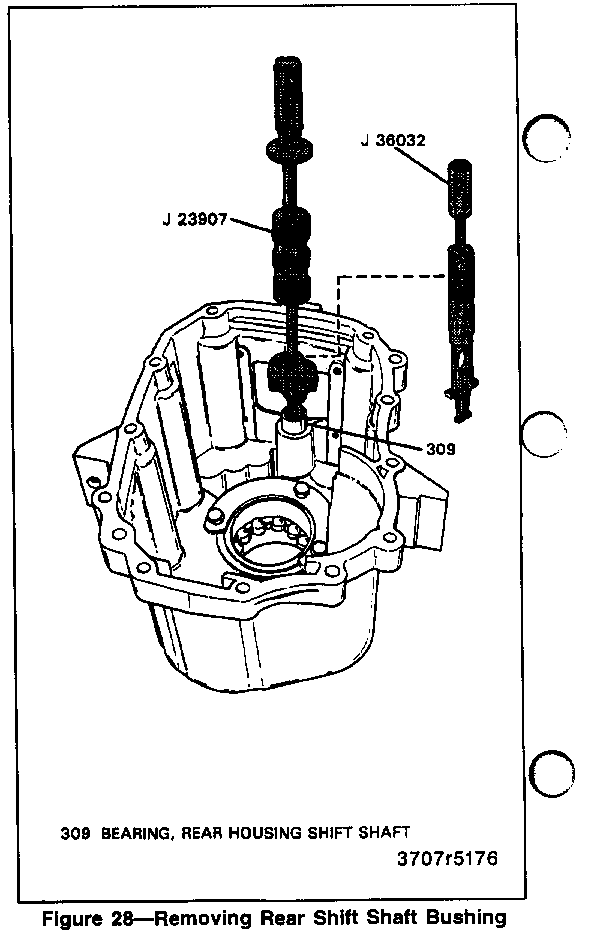
1. Rear housing shift shaft bearing (309), using J 23907 with pilot bearing puller (figure 28).
A. Position puller legs behind bearing lip.
B. Tighten.
C. Slide hammer out.
- If the bearing lip breaks off, position puller legs behind the inside (outer end) bearing lip and repeat procedure.
2. Drive out dowel pins.
3. Three bolts (306), output shaft bearing retainer (303), and bearing assembly (33), using brass drift (4WD models only) (figure 29).
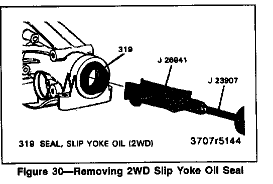
4. Slip yoke seal (319), using J 26941 and J 23907 (figure 30) (2WD models only).
5. Gasket material from the case using liquid gasket remover.
CLEANING AND INSPECTION
MAINSHAFT AND SYNCHRONIZERS
Clean
o All parts in a suitable solvent and air dry.
Important
o Do not spin dry ball bearings.
Inspect
1. Gears for:
o Cracks.
o Nicks.
o Chipped gear teeth or high spots (a small shiny spot on the gear teeth mating surface) that could cause gear noise.
2. Related surfaces on the gears like thrust faces and bearing surface diameters.
3. Synchronizer sleeves for:
o A sliding fit on the synchronizer hubs and for the hubs to have a force fit on the mainshaft splines. Replace the hub(s) if they do not require a force fit on the mainshaft.
4. Synchronizer springs and keys for:
o Damage.
5. Synchronizer rings for:
o Excess wear.
6. Synchronizer clutching teeth for:
o Wear.
o Scuffed.
o Nicked.
o Burred or broken teeth.
7. Speed gear clutching cones for:
o Synchronizer ring metal transfer.
8. All gear teeth for:
o Excess wear.
o The black phosphate coating will develop wear patterns. This is a normal condition.
9. Bearings and bearing surfaces for:
o Nicks.
o Burrs.
o Bent cages.
o Wear.
10. Lubricate all bearings and check for rough rotation.
o If scuffed, nicked, burred, scoring, or synchronizer ring metal transfer conditions cannot be removed with a soft stone or crocus cloth, replace the component and inspect mating parts.
o Lubricate all components as assembly progresses. Use lubricant 5W-30 GM P/N 1052931 or equivalent.
COUNTERSHAFT
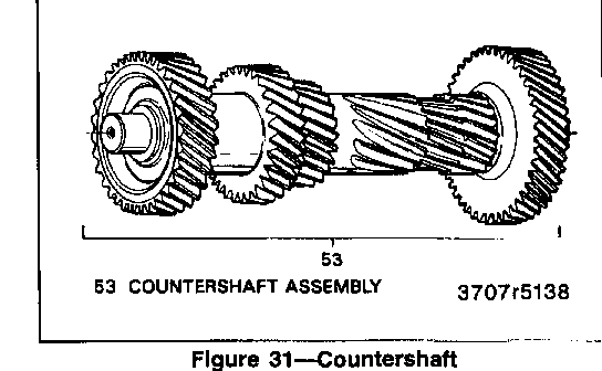
Clean (Figure 31)
o All parts in a suitable solvent and air dry.
Inspect (Figure 31)
1. Shaft (53) for cracks. Replace if these conditions exist.
2. Gear teeth (53) for scuffed, nicked, burred, broken teeth, or high spots (a small shiny spot on the gear teeth mating surface) that could cause gear noise.
3. Bearings (35) for roughness of rotation, burred, or pitted condition. Replace if these conditions exist.
4. Bearing races (202) for scoring, wear, or overheating.
o If scuffed, nicked, or burred conditions cannot be removed with a soft stone or crocus cloth, replace the component.
o Fifth gear CANNOT be pressed off the countershaft assembly (53). Replace as an assembly only.
REVERSE IDLER GEAR
Clean
o All parts in a suitable solvent and air dry.
Inspect
1. Gear teeth for scuffed, nicked, burred, broken teeth, or high spots (a small shiny spot on the gear teeth mating surface) that could cause gear noise.
2. Bearing assembly for roughness of rotation, burred, or pitted condition and cage damage. Replace if these conditions exist
3. Shaft, for scoring, wear, or overheating.
o If scuffed, nicked or burred conditions cannot be removed with a soft stone or crocus cloth, replace the component.
FRONT AND REAR HOUSINGS
Inspect
1. Bearing race bore, for wear, scratches, or grooves: if counter shaft bearing race bore is worn or damaged the rear housing MUST be replaced.
2. Bushings, for scores, burrs, roundness, or evidence of overheating.
Important
o Output shaft bushing cannot be serviced. Replace the rear housing if the bushing is worn or damaged (2WD models only).
3. Case for cracks, threaded opening for damaged threads, mounting faces for nicks, burrs, or scratches; if case is cracked, it must be replaced.
4. Machined mating surfaces for flatness. Check with a straight edge.
Important
o If scratches, grooves, or scoring cannot be removed with a soft stone or crocus cloth, replace the component.
o Clean up damaged threads with correct size tap.
SHIFT SHAFT AND FORK ASSEMBLIES
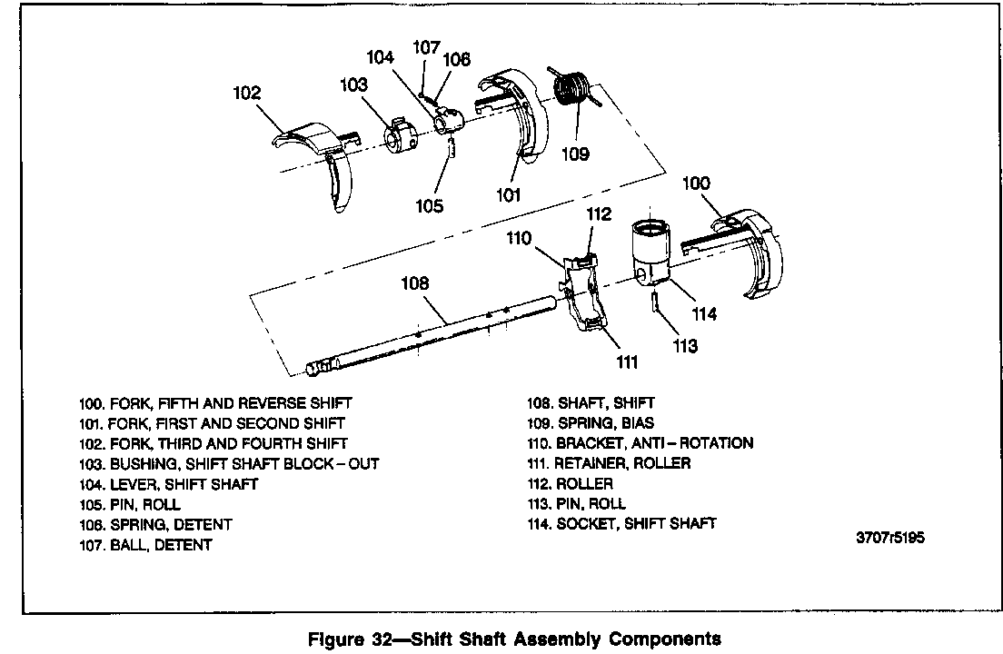
Clean (Figure 32)
o All parts in a suitable solvent and air dry.
Inspect
o Shift fork and inserts are serviced as an assembly only.
1. Shaft for wear or scoring.
2. Forks (100, 101 and 102) for wear, scoring, or distortion. The edges will turn black in color. This is a normal condition.
3. Shift lever and blockout bushing for wear.
4. Pins (105 and 113) for wear or distortion.
5. Shift shaft socket assembly (114) components for wear or distortion.
Important
o Wear or distortion requires replacement of assembly and close inspection of mating parts.
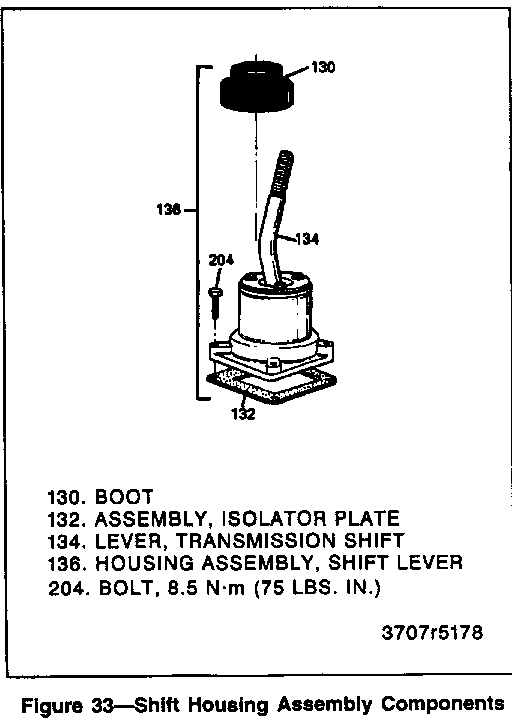
SHIFT LEVER HOUSING ASSEMBLY
Clean (Figure 33)
o The gasket material from the machined mating surface with liquid gasket remover.
Inspect (Figure 33)
o Anti-rotation plate for wear or distortion with a straight edge.
o The parts that compose the shift lever housing assembly (136) are serviceable as an assembly only. Replace the assembly for any shift lever rattle/buzz.
o Boot (130) for cracks, tears, or distortion. Replace the boot if any of these conditions exist.
o Machined mating surface for flatness. Check with a straight edge.
ASSEMBLY
INPUT SHAFT BEARING RETAINER ASSEMBLY
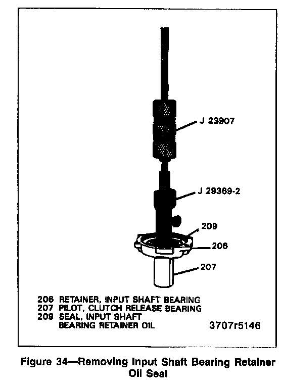
Remove or Disconnect (Figure 34)
Tools Required:
J 29369-2 Input Shaft Bearing Retainer Oil Seal Remover J 23907 Slide Hammer J 25070 Heat Gun J 36504 Input Shaft Bearing Oil Seal Installer Seal Replacement
1. Rubber seal lip with pliers.
o Exposing the metal lip:
A. Install J 29369-2 below metal lip of seal.
B. Expand to finger tight.
C. Turn five additional turns.
D. Install J 23907 into J 29369-2.
2. Input shaft bearing retainer oil seal (209).
A. Heat oil seal with J 25070 for minimum of 3 minutes.
B. Hold the clutch release bearing pilot with a heat resisting glove or equivalent. Remove the seal with a slide hammer.
3. Gasket material from the retainer (206) using liquid gasket remover.
Inspect
1. Clutch release bearing pilot for scoring, wear, or cracks, especially at the flange.
2. Retainer for wear or damage.
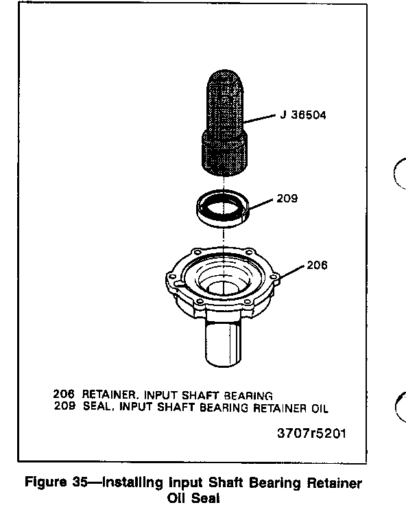
Install or Connect (Figure 35)
1. NEW oil seal (209) using J 36504.
o Fill between the seal lip with chassis grease.
REAR HOUSING ASSEMBLY
Assemble (Figures 1, 2, 36, and 37)
Tools Required:
J 36190 Drive Handle J 36503 Output Shaft Oil Seal Installer J 36506 Fifth and Reverse Detent Bushing Remover/Installer
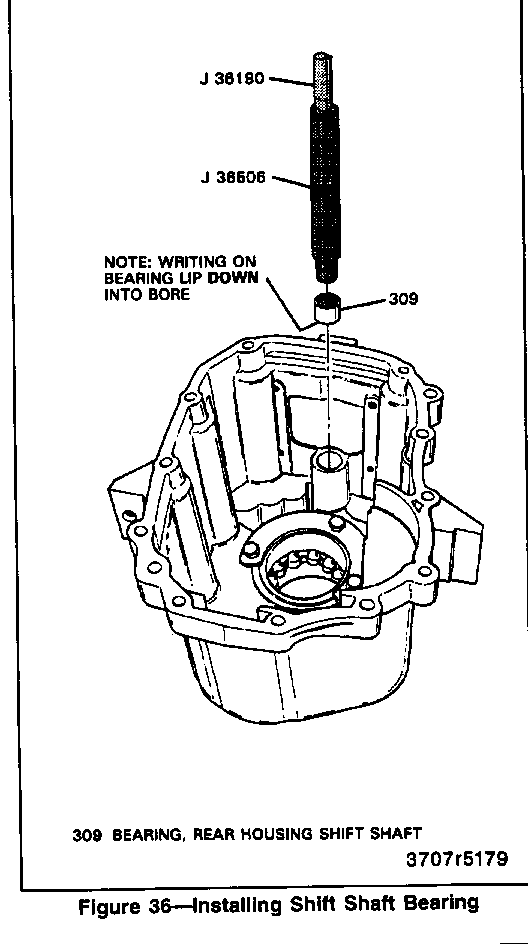
1. Rear housing shift shaft bearing (309) using J 36506 and J 36190 (figure 36).
A. Install bearing into bore so that the writing on bearing lip faces down.
B. Install flush.
NOTICE: Refer to "Notice" on page 7B1-1.
2. Bearing assembly (33) using brass drift (4WD models only).
o Output shaft bearing retainer (303).
o Three bolts (306). Apply threadlocker GM P/N 12345382 or equivalent to the threads.
Tighten
o Bolts (306) to 22 N-m (16 lbs. ft.).
3. Two dowel pins (321).
o Drive until flush.
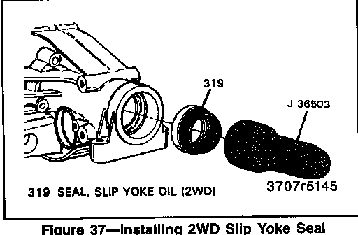
4. Slip yoke oil seal (319) using J 36503 (figure 37) (2WD models only).
o Fill between the seal lips with chassis grease.
FRONT HOUSING ASSEMBLY
Assemble (Figures 38, 39, and 40)
Tools Required:
J 36183 Input Shaft Press Tube with Cap J 36184 Adapter Press Tube Reducer J 36510 Clutch Fork Pivot Remover/Installer J 36507 Detent Bushing Remover and Installer J 36511 Oil Fill Plug Hex Bit (17 mm) J 36798-1 Shift Shaft Bushing Installing Tool J 36190 Drive Handle
1. Press in bearing (216) until snap ring is seated using J 36183, J 36184, and hydraulic press.
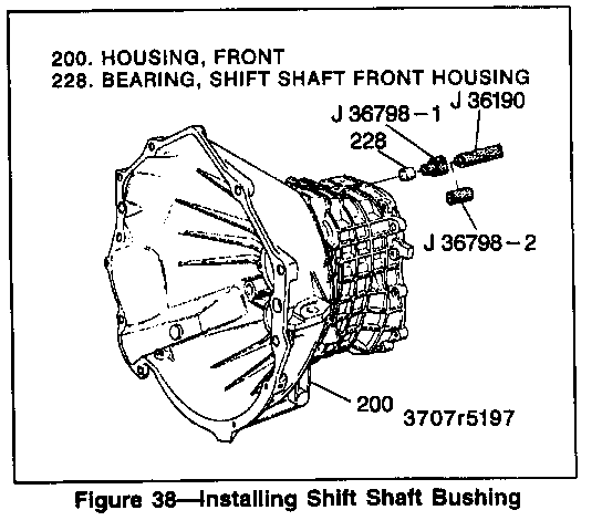
2. Shift shaft front housing bushings (228) using J 36798-1 and J 36190 (figure 38).
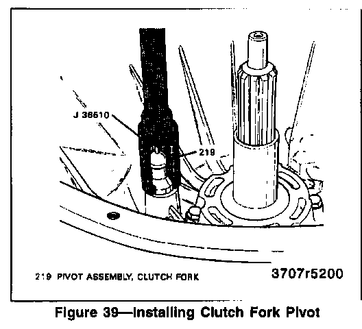
3. Clutch fork pivot assembly (219) using J 36510 and J 36190 (figure 39).
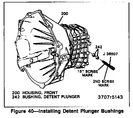
4. Two detent plunger bushings (242), using J 36507 (figure 40).
A. Install the first bushing until the second scribe mark on the tool is aligned with the housing.
B. Install the second bushing until the first scribe mark on the tool is aligned with the housing.
5. Breather assembly (223).
NOTICE: Refer to "Notice" on page 7B1-1.
6. Oil fill plug (222) and oil drain plug (225) using J 36511 (figure 27).
o Apply pipe sealant with Teflon GM P/N 1050280 or equivalent to the threads.
Tighten
o Drain plug to 60 N.m (44 lbs. ft.).
REVERSE IDLER GEAR ASSEMBLY
Assemble (Figure 23)
o Lubricate ail components as assembly progresses.
o Use Synchromesh Transmission Fluid GM P/N 12345349 or equivalent.
1. Bearing assembly (50).
2. Reverse gear (49).
o Extended part of the hub faces thrust washer.
3. Thrust washer (48).
4. NEW snap ring (47).
SYNCHRONIZER ASSEMBLY
Assemble (Figure 22)
1. Sleeve (8) or (20), onto hub (12), (21), or (28).
o Check scribe marks for correct positions.
o Remove spiral lock ring (27) for easier assembly (fifth-reverse only).
2. Spring (10) into key (11).
o Assembly into the hub.
3. Position assembly as in view A (figure 22).
4. Balls (9).
o Push the ball into the sleeve using a screwdriver.
o Push the sleeve (8) or (20) down just enough to retain the ball.
o Slide the sleeve up just enough to install each of the two remaining balls (on at a time).
5. Synchronizer rings (2).
o Make sure synchronizer ring tangs line up with the keys.
6. Center the hub, keys and balls by pushing on the synchronizer rings. Balls will "click" into position.
o Install spiral lock ring (27) (fifth-reverse only).
MAINSHAFT ASSEMBLY
Assemble (Figures 41 through 45)
Tools Required:
Hydraulic Press J 36183 Input Shaft Press Tube with Cap J 36184 Adapter Press Tube Reducer J 36513 Gear and Bearing Separator Plate J 22912-01 Separator Plate or Equivalent
Important
o The assembly of some components will require use of an assembly lube. It is recommended that TRANSJEL J 36850 or equivalent be used during assembly.
o Heat the 2WD speed sensor rotor (45) for 7-10 minutes at 120 degrees Celsius (250 degrees Fahrenheit) prior to installation during assembly procedures.
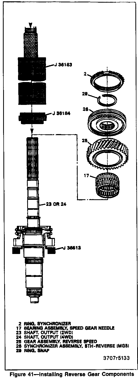
1. Bearing assembly (17) and reverse speed gear (25) (figure 41).
2. When pressing the fifth-reverse synchronizer assembly (26):
A. Manually align and engage splines.
B. Press until seated.
C. Be sure all shavings are removed.
3. Fifth-reverse synchronizer assembly (26) with synchronizer ring (2) using J 36183, J 36184, J 36513, and hydraulic press.
o Check scribe marks for correct positions.
o Position spiral lock ring (27) towards reverse speed gear (25).
4. NEW snap ring (29).
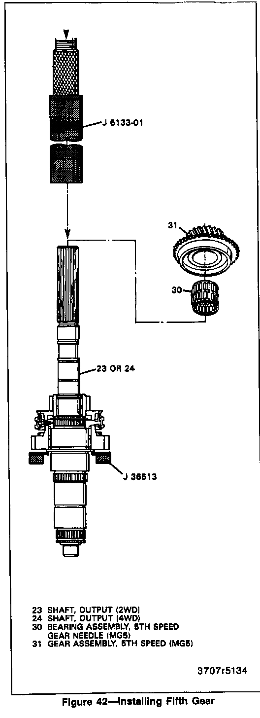
5. Bearing assembly (30) and fifth speed gear (31) (figure 42).
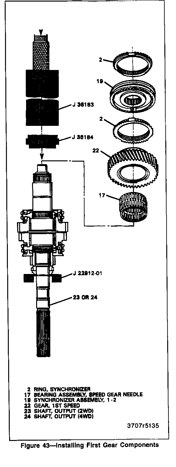
6. Bearing assembly (17) and first speed gear (22) (figure 43).
7. When pressing the first-second synchronizer assembly (19):
A. Manually align and engage splines.
B. Start press operation, STOP before tangs engage.
C. Lift and rotate gear (2-2) to engage synchronizer ring (2).
D. Continue to press until seated.
E. Be sure all shavings are removed.
8. First-second synchronizer assembly (19) with both synchronizer rings (2) using J 36183, J 36184, J 22912-01, and hydraulic press.
o Check scribe marks for correct positions.
Important
o The groove on the outside of the sleeve MUST GO TOWARDS THE SECOND SPEED GEAR to prevent gear clash during first and second gear shifts. The teeth of the sleeve have different angles.
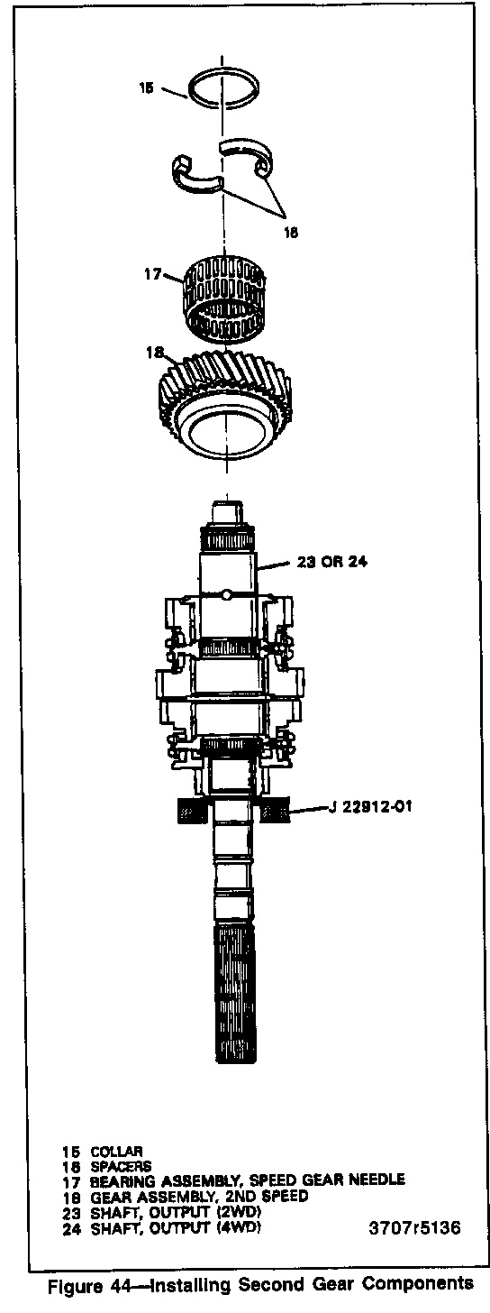
9. Bearing assembly (17) and second speed gear (18) (figure 44).
o Make sure bearing cage is together.
10. Spacers (16) and collar (15).
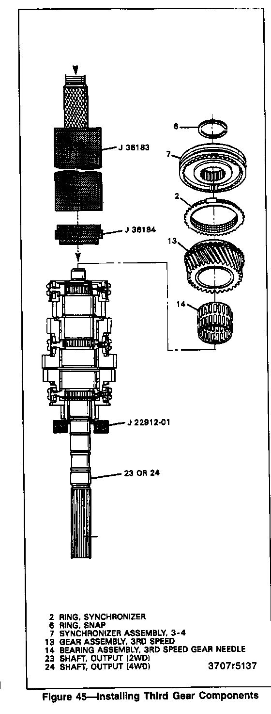
11. Bearing assembly (14) and third speed gear (13) (figure 45).
12. When pressing the third-fourth synchronizer assembly (7):
A. Manually align and engage splines.
B. Start press operation, STOP before tangs engage.
C. Lift and rotate gear (13), to engage synchronizer ring (2).
D. Continue to press until seated.
E. Be sure all shavings are removed.
13. Third-fourth synchronizer assembly (7) with both synchronizer rings (2) using J 36183, J 36184, J 22912-01, and hydraulic press.
14. NEW snap ring (6).
TRANSMISSION ASSEMBLY
Assemble (Figures 46 through 53)
Tool Required:
J 25070 Heat Gun (2WD models only) J 36515-10 Retainer Alignment Cables (2WD models only) J 36502 4WD Oil Seal Installer J 36502-2A 4WD Seal Protector J 36515 Assembly Pallet J 36515-16 Countershaft Adapter J 36515-15 Mainshaft Adapter J 3289-20 Base Holding Fixture J 8763-02 Holding Fixture C-Clamp J 8763-21 Balance Bracket for C-Clamp J 6133-01 Speedometer Rotor Installer (2WD models only) J 36824 Transmission Holding Fixture Adapters
NOTICE: For steps 13, 18, 30, 36, 39, 40, 41, 42, and 44, refer to "Notice" on page 7B1-1.
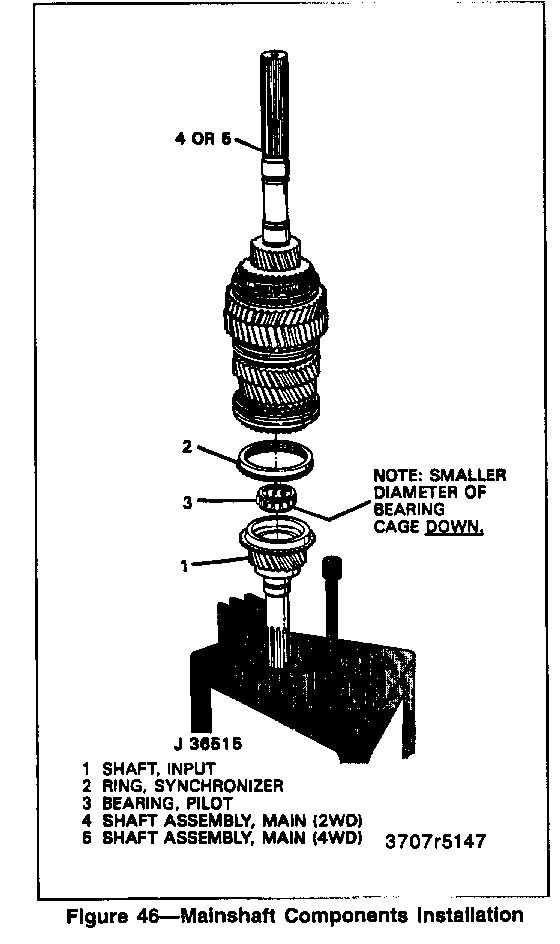
1. Pilot bearing (3) into input shaft (1) (figure 46).
A. Turn the smaller diameter of the bearing cabe toward the input shaft.
B. Retain with TRANSJEL J 36850 or equivalent.
2. Position onto J 36515-15/J 36515 fixture:
A. Input shaft (1).
B. Pilot bearing (3).
C. Synchronizer ring (2).
D. Mainshaft assembly (4) (2WD) or (5) (4WD).
3. Position countershaft (53) onto J 36515-16 fixture (figure 14).
4. Reverse idler assembly (46).
5. Output shaft bearing assembly (33) (2WD models only).
6. New snap ring (44).
7. Install on main shaft assembly (4) or (5):
A. First-second shift fork (101).
B. 5-reverse shift fork (100).
Important
o Steps 8 through 13 are for 2WD models only. Steps 14 and is for 4WD models only.
8. Snap-ring (43) (figure 14) (2WD models only).
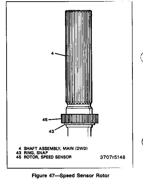
9. Speed sensor rotor (45) HEATED (2WD models only) (figure 47).
o If necessary seat with J 6133-01.
Important
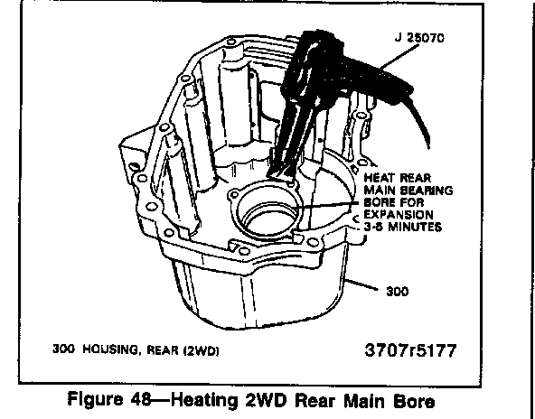
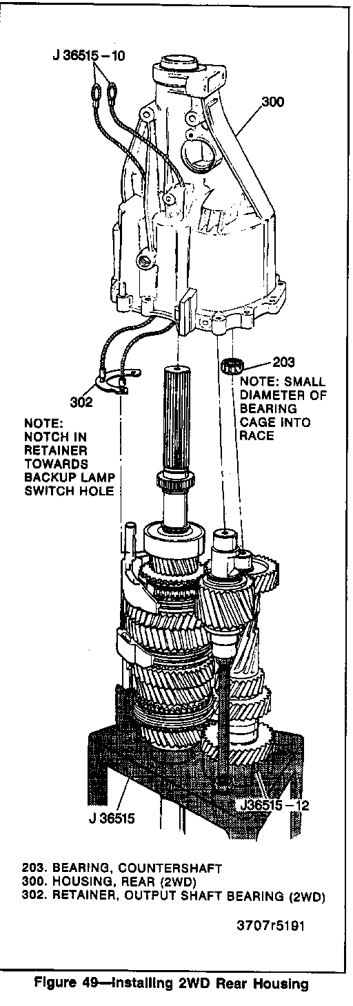
o The 2WD rear housing output shaft bearing assembly bore MUST be heated for 3 to 5 minutes with J 25070 before assembly (figure 48).
10. J36515-10 through bolt (304) and (305) holes in the rear housing (figure 49) (2WD models only).
o Screw into the output shaft bearing retainer (302).
o Notch in retainer towards oil delivery tube assembly (307).
11. Bearing (203). (2WD models only.)
A. Install in bearing race (202) of the housing, with the smaller diameter of the bearing cage into the bearing race.
B. Retain with TRANSJEL J 36850 or equivalent.
Important
o Press each roller towards the race to secure them for easier assembly.
12. Rear housing assembly (300) (2WD models only).
A. Make sure the reverse idler shaft is lined up with the hole in the case.
B. Rotate back and fourth while pulling down.
C. Pull up on J 36515-10 while installing rear housing.
Important
o Bring the housing straight down. If resistance is felt at about 7 mm (1/4 in.), then the rollers (203) are cocked. Repeat above procedures to install. Do not force housing down.
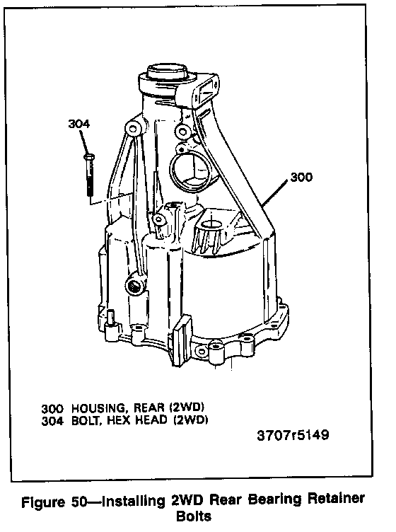
13. Bolts (304) (figure 50) (2WD models only).
A. Apply pipe sealant with Teflon GM P/N 1050280 or equivalent to the bolt holes of the rear housing.
B. Apply threadlocker GM P/N 12345382 to bolt threads.
C. Remove J 36515-10.
Tighten
o Bolts (304) to 22 N-m (16 lbs. ft.).
14. Bearing (203) (figure 13) (4WD models only).
A. Install in bearing race (202) of the housing.
B. Install the smaller diameter of the bearing cage into the bearing race.
C. Retain with TRANSJEL J 36850 or equivalent.
D. Press each roller towards the race to secure them for easier assembly.
15. Rear housing assembly (301) (4WD models only) (figure 13).
A. Make sure the reverse idler shaft is lined up with the hole in the case.
B. Rotate back and forth while pulling down.
Important
o Bring the housing straight down. If resistance is felt at about 7 mm (1/4 in.), then the rollers (203) are cocked. Repeat above procedures to install. Do not force the housing down.
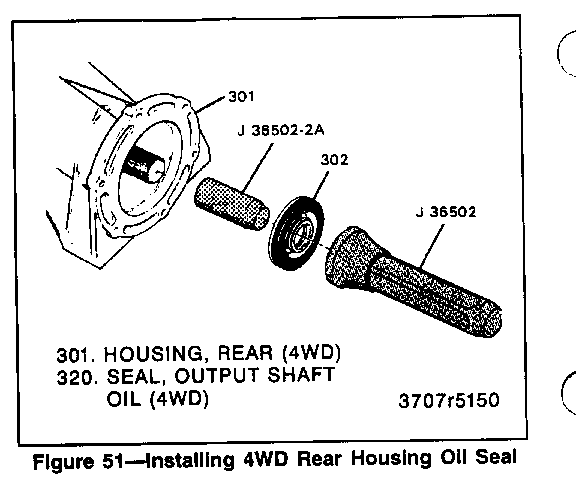
o Install seal protector J 36502-2A onto output shaft.
16. Output shaft oil seal (320) using J 36502 (figure 51) (4WD models only).
A. Fill between the seal lip with chassis grease.
B. Remove seal protector J 36502-2A.
Important
o The remaining assembly procedures apply to both 2WD and 4WD models.
17. Lay the unit down on the workbench and remove J 36515, J 36515-15, and J 36515-16.
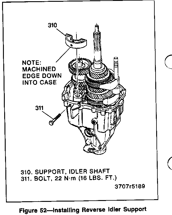
18. Idler shaft support (310) and bolt (311) (figure 52).
A. Line up the bolt threads in the idler shaft support with bolt hole.
B. Apply pipe sealant with Teflon GM P/N 1052080 or equivalent to the bolt hole.
C. Apply threadlocker GM P/N 1235382 or equivalent to the bolt threads.
D. Hold reverse idler shaft against idler support while torquing.
Tighten
o Bolt to 22 N-m (16 lbs. ft.).
19. Position J 8763-21, J 8763-02, and J 36824 onto the transmission case (figure 11).
20. Third-fourth shift fork (102) onto the third-fourth synchronizer sleeve (8).
o Align all three insert notches.
21. Shift shaft (108) into third-fourth shift fork (102) with detent reliefs in shaft pointing out (figures 1 and 2).
22. Shift lever (104) and block-out bushing (103) onto the shift shaft (108).
23. Shift shaft (108) through first-second shift fork (101).
24. Biasing spring (109), anti-rotation bracket (110), and shift socket (114) onto the shift shaft (108).
o Slide the shift shaft (108) all the way into the case (300) or (301).
25. New roll pin (105) into shift lever.
o Rotate shift shaft and shift lever/blockout bushing assembly until roll pin holes are aligned and horizontal.
o Install pin (105) until flush with the shift lever (104).
26. Fork insert detent spring (106) and ball (107) into hole in the shift lever (104).
o Rotate shift shaft (108) counter-clockwise until shift lever (104) is almost into fifth-reverse insert notch.
o Install spring (106) and ball (107) into shift lever (104).
o Rotate shift shaft (108) until shift lever (104) aligns with 3-4 insert.
27. Shift socket (114) to shift shaft roll pin (113).
o Align holes in the shift socket (114) and shift shaft (108).
o Drive roll pin (113) until it is flush with the bottom of the shift socket (114).
Important
o Use the second (middle) roll pin hole on the MGS transmission and the rear roll pin hole on the MY2 transmission.
28. Biasing spring (109) tangs to the anti-rotation bracket (110) using a screwdriver.
o Make sure the shifter is in neutral and anti-rotation bracket rollers (112) are level with machined surface of case opening.
29. Gasket eliminator to both sides of the anti-rotation roller plate and install to case opening.
o Thin side of plate as viewed from the top should be installed towards the left side of the transmission.
30. Shift tower (136) and bolts (204) (figure 33).
Tighten
o Shift tower bolts to 10 N-m (89 lbs. in.).
31. Countershaft bearing (35) to countershaft race (figure 10).
Important
A. Install smaller diameter of bearing cage into the bearing race.
B. Press each roller into cage and retain with TRANSJEL J 36850 or equivalent.
C. Apply TRANSJEL J 36850 or equivalent to bearing race on input shaft.
32. Front housing (200) (figure 10).
Important
o Bring the housing straight down. If resistance is felt at about 7 mm (1/4in.), then the rollers (35) are cocked. Repeat steps 28, 29, and 30. Do not force down the housing.
33. Two dowels (321) (figures 1 and 2).
34. Bolts (312) (figure 10).
o Do not tighten.
o Tip vertically.
35. NEW snap ring (210) (figure 9).
o It may be necessary to pull out on the input shaft to install the snap ring.
o Apply gasket maker GM P/N 1052943 or equivalent to the inside of the bolt hole pattern.
Important
o DO NOT APPLY too much gasket maker around the oil drain back hole. This could clog the hole causing a low fluid flow through the bearing resulting in premature bearing failure.
36. Input shaft bearing retainer assembly (205) and six bolts (204).
o Make sure oil drain back hole is lined up with the hole in the housing.
Tighten
o Bolts (204) to 8.5 N-m (75 lbs. in.).
37. Shift shaft detent plunger (243), shift shaft detent spring (244), and plug (245) using brass drift (figure 53).
o Apply pipe sealant with Teflon GM P/N 1052080 or equivalent to the plug.
38. Install new 0-ring (315) onto electronic speed sensor assembly (316) (2WD models only).
o Coat the 0-ring with a thin film of transmission fluid.
39. Electronic speed sensor assembly (316) and bolt (317) (2WD models only).
Tighten
o Bolt (317) to 9 N.m (80 lbs. in.).
40. Backup lamp switch assembly (313).
o Apply pipe sealant with Teflon GM P/N 1052080 or equivalent to the threads.
Tighten
o Switch (313) to 9 N-m (80 lbs. in.).
41. Remove J 8763-02 and J 36824.
Tighten
o Bolts (312) (figure 5) to 35 N-m (26 lbs. ft.).
42. Blockout bushing anchor bolt (236) (figures 1 and 2).
Tighten
o Anchor bolt to 25 N-m (18 lbs. ft.).
43. Fill transmission with Synchromesh Transmission Fluid or the equivalent.
44. Oil fill plug (222).
Tighten
o Oil fill plug (222) to 60 N-m (44 lbs. ft.).
SPECIFICATIONS FASTENER TIGHTENING SPECIFICATIONS ---------------------------------- N-m Lbs. Ft. Lbs. In. --- -------- -------- Backup Lamp Switch 9 - 80 Blockout Bushing Anchor Bolt 25 18 - Front to Rear Housing Bolts 35 26 - Idler Shaft Support Bolt 22 16 - Input Shaft Bearing Retainer Bolts 8.5 - 75 Oil Drain Plug 60 44 - Oil Fill Plug 60 44 - Output Shaft Bearing Retainer Bolts 22 16 - Shift Tower Bolts 10 - 89 Speed Sensor Bolt 9 - 80
LUBRICATION SPECIFICATIONS
Capacity 1.98L (2.0 qts.) Type Recommended Synchromesh Transmission Fluid
General Motors bulletins are intended for use by professional technicians, not a "do-it-yourselfer". They are written to inform those technicians of conditions that may occur on some vehicles, or to provide information that could assist in the proper service of a vehicle. Properly trained technicians have the equipment, tools, safety instructions and know-how to do a job properly and safely. If a condition is described, do not assume that the bulletin applies to your vehicle, or that your vehicle will have that condition. See a General Motors dealer servicing your brand of General Motors vehicle for information on whether your vehicle may benefit from the information.
