SERVICE MAN.UPDATE SEC.5A4 4WAL BRAKE SYSTEM

SUBJECT: SERVICE MANUAL UPDATE SECTION 5A4 - 4WAL BRAKE SYSTEM
VEHICLES AFFECTED: 1990-91 M/L VANS, 1991 S/T (REVISED 4WAL BRAKE BLEEDING PROCEDURE
THIS BULLETIN IS BEING REVISED TO UPDATE THE BLEED PROCEDURE AND TO ADD 1991 MODEL S/T 4-DOOR UTILITY VEHICLES AND 1991 M/L VANS. THIS BULLETIN ALSO UPDATES INFORMATION IN 1990 M/L SERVICE MANUAL X9030, 1991 M/L SERVICE MANUAL X9130, 1991 S/T SERVICE MANUAL X9129, AND STG RWAL UPDATE 4WAL PREVIEW MANUAL 15005.05-2. PLEASE PLACE A COPY OF THIS BULLETIN IN EACH MANUAL.
The following brake bleeding procedure is to be used on ALL 1990-91 M/L Vans and S/T four door utility vehicles equipped with 4WAL.
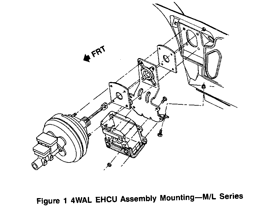
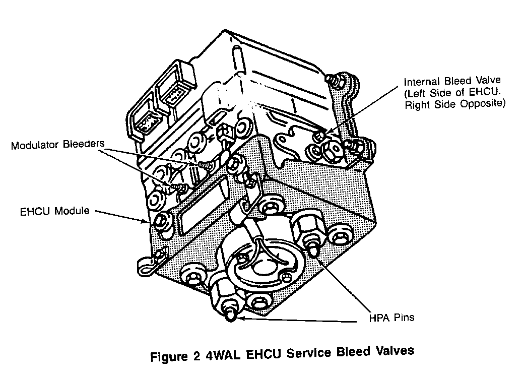
It is necessary to bleed the brake system whenever air is introduced into the system. If the EHCU (Electro-Hydraulic Control Unit) module has not been replaced normal brake system bleeding procedures may be used. If the EHCU has been replaced, or if it is suspected that air has been introduced into the EHCU the following steps should be taken.
IMPORTANT: THIS REVISED PROCEDURE ELIMINATES THE NEED TO MANUALLY BLEED THE ---------- EHCU. THE TECH 1 FUNCTION TEST WILL PURGE THE MODULE OF ANY TRAPPED AIR.
1. Bleed the brake system in the conventional manner using either vacuum, pressure or manual bleeding. The conventional pressure bleed procedure is given at the end of this bulletin. Technicians should always maintain a full master cylinder both during and after bleeding.
2. Using a Tech 1 scan tool with a serial number above xx002000 along with tool number TK 2650 (4WAL cartridge, special RWAL/ 4WAL adapter, and harness) perform THREE (3) system function tests (reference Pg. II-3-10 of RWAL Update 4WAL Preview Manual 15005.05-2.
IMPORTANT: DURING THE FUNCTION TESTS THE BRAKE PEDAL MUST BE FIRMLY ---------- DEPRESSED, THIS WILL PURGE ANY AIR TRAPPED IN THE EHCU HIGH PRESSURE ACCUMULATOR, LOW PRESSURE ACCUMULATOR AND PUMP CIRCUITS.
3. Re-Bleed the vehicle brake system as instructed in step one to purge any air introduced to the brake lines from the EHCU purging.
4. Confirm that no soft or spongy pedal action is observed. Repeat steps 1-4 if pedal response indicates air remains in the system.
IMPORTANT: Failure to follow this procedure accurately may result in ---------- immediate soft pedal after the first anti-lock stop.
PRESSURE BLEEDING PROCEDURE
The pressure bleeding equipment must be of the diaphragm type. It must have a rubber diaphragm between the air supply and the brake fluid to prevent air, moisture, oil, and other contaminants from entering the hydraulic system. Use extreme care to prevent brake fluid from contacting any painted surface.
Tools Required: J29567 Brake Bleeder Adapter --------------- J35856 Combination Valve Depressor
1. Fill the pressure tank at least 1/3 full of brake fluid. The bleeder, must be re-bled each time fluid is added.
o Charge the bleeder to 140-170 kPa (20-25 psi)
2. Use J35856 to depress and hold the valve stem on the combination valve during the bleeding operation.
3. Install the bleeder adapter.
4. Bleed each wheel in the following sequence.
o Right rear o Left rear o Right front o Left front
5. Connect the hose from the bleeder to the adapter at the master cylinder.
6. Open the tank valve.
7. Attach a hose to a brake bleeder screw.
8. Immerse the opposite end of the hose into a container partially filled with clean brake fluid.
9. Open the bleeder screw at least 3/4 of a turn and allow the fluid to flow until no air is seen in the fluid.
10. Close the bleeder screw.
11. Repeat steps 7 through 10 at all the wheels.
12. Check the brake pedal for "sponginess", repeat the entire bleeding procedure if this condition is found.
13. Remove J35856.
14. Disconnect the line from the bleeder adapter.
15. Remove the bleeder adapter.
16. Fill the master cylinder to the proper level with brake fluid.


General Motors bulletins are intended for use by professional technicians, not a "do-it-yourselfer". They are written to inform those technicians of conditions that may occur on some vehicles, or to provide information that could assist in the proper service of a vehicle. Properly trained technicians have the equipment, tools, safety instructions and know-how to do a job properly and safely. If a condition is described, do not assume that the bulletin applies to your vehicle, or that your vehicle will have that condition. See a General Motors dealer servicing your brand of General Motors vehicle for information on whether your vehicle may benefit from the information.
