Circuit Description
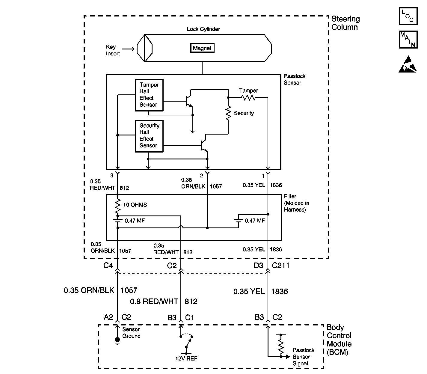
The Passlock™ system is designed in order to prevent vehicle operation if the correct ignition key is not used in order to start the vehicle. The ignition key allows the lock cylinder to turn. Once the lock cylinder turns, the Passlock™ sensor (located inside the ignition switch assembly) sends an analog voltage code to the body control module (BCM). If the BCM receives the correct analog voltage code from the Passlock™ sensor, the BCM sends a class 2 serial data password to the vehicle control module (VCM). This action allows the vehicle to start.
Conditions for Setting the DTC
| • | The Passlock™ system uses 10 valid data values. The BCM only recognizes the last learned value as the correct value. |
| • | The BCM inspects the Passlock™ data for incorrect but valid data values during a start attempt. |
| • | The BCM inspects Passlock™ data for incorrect but valid data values for 1 second when the vehicle is not in the learn mode. |
Action Taken When the DTC Sets
| • | The vehicle will not start if the fault occurs before you start the vehicle. The security telltale will be FLASHING. |
| • | The vehicle will start if the fault occurs after the vehicle is running. The vehicle will be in the Fail Enable mode and the security telltale wil be ON. |
Conditions for Clearing the DTC
| • | All current DTCs (except B3031) clear once an ignition cycle occurs without the fault recurring. |
| • | A history DTC clears once 100 concurrent ignition cycles occur without the fault recurring. |
| • | Use a scan tool in order to clear history and current DTCs. |
Diagnostic Aids
| • | Use the scan tool in order to inspect the Passlock™ data voltage and the Passlock™ code. |
| • | When the ignition switch is turned from the OFF position to the RUN position, the security telltale will turn ON steady and then turn OFF after 3 seconds. |
| • | Perform a visual inspection of the wiring. |
| • | Perform a visual inspection of the connectors. |
| • | Inspect the Passlock™ sensor harness for an intermittent or poor connector, including the inline connector. |
Test Description
The numbers below refer to the step numbers on the diagnostic table:
Step | Action | Value(s) | Yes | No | ||||||||||||||||||||
|---|---|---|---|---|---|---|---|---|---|---|---|---|---|---|---|---|---|---|---|---|---|---|---|---|
1 | Did you perform the Theft Deterrent (VTD) Diagnostic System Check? | -- | Go to Step 2 | |||||||||||||||||||||
2 |
Does the scan tool display DTC B2960 as a current DTC? | -- | Go to Step 3 | Go to Testing for Intermittent Conditions and Poor Connections | ||||||||||||||||||||
3 | Does the scan tool display DTC B2947, B2948, B2957, or B2958? | -- | Go to Step 4 | |||||||||||||||||||||
4 | Have you replaced the Passlock™ sensor on this vehicle? | -- | Go to Step 5 | Go to Step 6 | ||||||||||||||||||||
5 | Have you performed a Passlock™ learn procedure after replacing the Passlock™ sensor? | -- | Go to Step 6 | Go to Step 9 | ||||||||||||||||||||
With a scan tool, observe the Passlock™ data voltage for one minute. Does the scan tool indicate that the Passlock™ data voltage is changing more than the specified value? | +/- 0.02v | Go to Step 7 | Go to Step 9 | |||||||||||||||||||||
7 | Inspect for poor connections at the Passlock ™ sensor. Refer to Testing for Intermittent Conditions and Poor Connections and Connector Repairs in Wiring Systems. Did you find and correct the condition? | -- | Go to Step 10 | Go to Step 8 | ||||||||||||||||||||
8 | Replace the Passlock™ sensor in the electronic column lock module assembly. Use the appropriate procedure from the following list:
Did you complete the replacement? | -- | Go to Step 9 | -- | ||||||||||||||||||||
9 | Perform one of the following Passlock™ learn procedures:
Is the repair complete? | -- | Go to Step 10 | -- | ||||||||||||||||||||
10 |
Does the DTC reset? | -- | Go to Step 3 | System OK |
