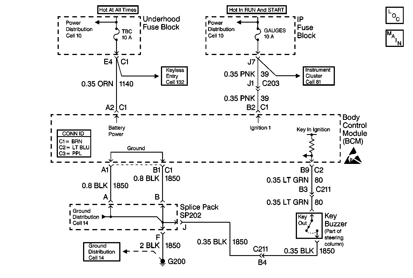
Circuit Description
The body control module (BCM) monitors the key-in ignition switch on CKT 80 in order to determine if the ignition key is in the ignition switch. This signal provides an audible warning to the driver that the key is still in the ignition switch and provides exit lighting when the key is removed.
Conditions for Setting the DTC
| • | CKT 80 is shorted to battery voltage or CKT 80 is open and the ignition switch is in the RUN position. |
| • | The Ignition 1 (IGN 1) circuit is shorted to battery voltage and the ignition key is not in the ignition switch. |
| • | Any of the above conditions may exist. |
| • | The system voltage is between 9.0-16.0 volts. |
| • | The above conditions exist for 0.5 seconds. |
Action Taken When the DTC Sets
| • | The Key-In warning chime will not operate correctly. |
| • | The exit lighting will not operate correctly. |
| • | The content theft will not function properly when IGN 1 is shorted to battery voltage. |
Conditions for Clearing the MIL/DTC
| • | A current DTC will clear after the next ignition cycle that does not contain a fault. |
| • | A history DTC will clear after 100 consecutive ignition cycles without a fault present. |
| • | History and current DTCs may be cleared using a scan tool. |
Diagnostic Aids
| • | Always diagnose the first DTC that is listed on the scan tool. |
| • | Verify that the scan tool displays DTC B2961 as a current code before you perform diagnostics. |
| • | If CKT 80 has been shorted to battery voltage, complete the following steps: |
| - | Inspect the key in ignition switch for damage. |
| - | Repair the short to battery. |
| • | Inspect for loose or poor connections at all of the related components. |
| • | Refer to Intermittents and Poor Connections Diagnosis in Wiring Systems. |
Test Description
The numbers below refer to the step numbers on the diagnostic table.
-
This step determines if the circuit is shorted to battery voltage.
-
This step determines if the BCM is defective.
-
This step tests CKT 80 for an open between the BCM and the key-in ignition switch connector.
-
This step determines if one of the following conditions exists:
| • | CKT 1850 is open between the key-in ignition switch connector and ground. |
| • | The key-in ignition switch is open. |
Step | Action | Value(s) | Yes | No |
|---|---|---|---|---|
1 | Did you perform the BCM Diagnostic System Check? | -- | Go to Step 2 | |
Does the J 39200 DMM display battery voltage? | -- | Go to Step 9 | Go to Step 3 | |
Does the KEY IN IGNITION parameter display the specified value on the scan tool? | YES | Go to Step 4 | Go to Step 10 | |
Does the J 39200 DMM display battery voltage? | -- | Go to Step 5 | Go to Step 8 | |
Using a J 39200 DMM, backprobe between CKT 80 (LT GRN) and CKT 1850 (BLK) at the key-in switch connector. Does the J 39200 DMM display battery voltage? | -- | Go to Step 6 | Go to Step 7 | |
6 | Replace the ignition switch. Is the repair complete? | -- | Go to Step 11 | -- |
7 | Locate and repair CKT 1850 (BLK) from the key-in ignition switch to ground. Is the repair complete? | -- | Go to Step 11 | -- |
8 | Locate and repair the open in CKT 80 (LT GRN) between the BCM and the key-in ignition switch. Is the repair complete? | -- | Go to Step 11 | -- |
9 |
Is the repair complete? | -- | Go to Step 11 | -- |
10 |
Is the repair complete? | -- | Go to Step 11 | -- |
11 | Clear the DTCs. Is the repair complete? | -- | -- |
