The vehicle control module (VCM) is located in the engine compartment. The VCM is the control center for the engine component systems which effect engine operation. The VCM constantly monitors and processes information from the various information sensors and switches. The VCM then sends the necessary electrical responses to control the various control system components. Review the wiring diagrams in order to determine which systems are controlled by the VCM. The VCM has the ability to perform on-board diagnostic tests on itself, the information system components, and certain control system components. The VCM has the ability to alert the driver of a malfunction by illuminating a malfunction indicator lamp (MIL). The VCM has the ability to store certain information pertaining to a malfunction, including diagnostic trouble codes (DTCs). Using serial data communication, a scan tool can retrieve this information in order to be viewed by the technician. The technician can use this information in order to identify, diagnose, and verify the repair of the malfunction. The VCM is sometimes referred to as the control module.
Memory
The VCM control calibrations for a particular vehicle are based on the vehicle identification number (VIN). The calibrations are stored in the electrically erasable programmable read-only memory (EEPROM). The EEPROM is part of the VCM and can not be replaced. The EEPROM can be reprogrammed using the Techline equipment. The electronic ignition control module is located in the VCM. The knock sensor (KS) module contains the knock sensor system calibrations. The knock sensor module is not part of the VCM and is serviced separately from the VCM. The VCM has the ability to make corrections in the fuel control system in order to allow for minor vehicle variations. This information is stored in the random access memory (RAM). RAM needs a constant voltage supply to be retained. The short term fuel trim and the long term fuel trim are stored in RAM. When the battery is disconnected during service of the vehicle, this memory is lost and the driver may notice a change in the performance of the vehicle. In order to restore this memory, perform the following steps:
- Start the engine.
- Allow the engine to reach normal operating temperature.
- Drive the vehicle under idle, partial throttle, and moderate acceleration conditions.
- Continue until normal vehicle performance returns.
Control Module Service Precautions
Notice: The VCM must be maintained at a temperature below 85°C (185°F) at all times. This is most critical when the vehicle is put through a paint baking process. The VCM becomes inoperative if its temperature 85°C (185°F). It is recommended that temporary insulation be placed around the VCM or removed from the vehicle during the time the vehicle is in a paint oven or other high temperature process. Do not operate the vehicle if the insulation is on the VCM.
Important: Do not overload any circuit. The control module is designed to withstand the normal current draws, or amps, that are associated with the vehicle operations. Do not ground any of the control module circuits unless instructed to do so. Do not apply voltage to any of the control module circuits when testing for an open circuit or testing for a short circuit.
Basic Knowledge And Tools Required
In order to effectively use this service information, a general understanding of basic electrical circuits and circuit testing tools is required. The technician must be familiar with circuit diagrams and the meaning of terms such as voltage, ohms, amps, and the basic theories of electricity. The technician must understand what happens in an open circuit and a shorted circuit.
A complete listing of the tools needed to diagnose and repair the system is located in Special Tools.
Use of Circuit Testing Tools
Notice: Since the VCM is located under the hood, its connectors are sealed and cannot be backprobed as in the previous model years. Do not attempt to backprobe as a connector or seal damage could occur.
Important: Do not use a test lamp in order to diagnose the control module system unless specifically instructed by the diagnostic procedures. Use the J 35616-A connector test adapter kit whenever the diagnostic procedure instructs the technician to probe any of the connectors.
Aftermarket (Add-On) Electrical and Vacuum Equipment
Aftermarket, add-on, electrical, and vacuum equipment is any device installed onto a vehicle after the vehicle has left the factory that connects to the electrical circuits or vacuum hoses of the vehicle.
Notice: Do not attach add-on vacuum operated equipment to this vehicle. The use of add-on vacuum equipment may result in damage to vehicle components or systems.
Notice: Connect any add-on electrically operated equipment to the vehicle's electrical system at the battery (power and ground) in order to prevent damage to the vehicle.
Add-on electrical equipment installed as instructed can cause the system to malfunction.
Add-on electrical equipment not connected to the vehicle electrical circuits can cause the system to malfunction. Examples of these types of equipment include the following:
| • | Portable telephones |
| • | Portable radios |
Disconnect all add-on equipment in order to diagnose a malfunction.
Electrostatic Discharge Damage
Notice: Do not touch the connector pins or soldered components on the circuit board in order to prevent possible electrostatic discharge (ESD) damage to the PCM.
In order to prevent electrostatic discharge damage to the VCM, do not touch the connector pins or the soldered components on the circuit board.
Visual and Physical Underhood Inspection
Carefully perform a visual and physical underhood inspection when performing any diagnostic procedure. This inspection will often lead to repairing a malfunction without further action.
System Status and Drive Cycle For Inspection/Maintenance (I/M)
Important: The System Status display indicates whether or not a diagnostic test is completed. Diagnose and repair the system if any of the on-board diagnostic tests have failed the last test. Verify that all of the required diagnostic tests pass prior to returning the vehicle to the customer. Use the Typical Drive Cycle table as a guide to complete the System Status test associated with inspection and maintenance (I/M).
Some areas require that certain vehicles run and pass on-board diagnostic test of particular emissions systems.
Using a scan tool, the technician has the ability to monitor the System Status of the following systems:
| • | The catalyst monitoring system |
| • | The evaporative emission (EVAP) system |
| • | The heated oxygen sensor (HO2S) |
| • | The heated oxygen sensor (HO2S) heater |
| • | The exhaust gas recirculation (EGR) system |
| • | The air injection reaction (AIR) system, if equipped |
Diagnostic Time Schedule for I/M Readiness | |
|---|---|
Vehicle Drive Status | What is Monitored? |
Cold Start, coolant temperature less than 50°C (122°F) | -- |
Idle 2.5 minutes in Drive (Auto) Neutral (Man), A/C and rear defogger ON | HO2S Heater, Misfire, Secondary Air, Fuel Trim, EVAP Purge |
A/C off, accelerate to 90 km/h (55 mph), 1/2 throttle. | Misfire, Fuel Trim, Purge |
3 minutes of Steady State - Cruise at 90 km/h (55 mph) | Misfire, EGR, Secondary Air, Fuel Trim, HO2S, EVAP Purge |
Clutch engaged (Man), no braking, decelerate to 32 km/h (20 mph) | EGR, Fuel Trim, EVAP Purge |
Accelerate to 90-97 km/h (55-60 mph), 3/4 throttle | Misfire, Fuel Trim, EVAP Purge |
5 minutes of Steady State Cruise at 90-97 km/h (55-60 mph) | Catalyst Monitor, Misfire, EGR, Fuel Trim, HO2S, EVAP Purge |
Decelerate, no breaking. End of Drive Cycle | EGR, EVAP Purge |
Total time of OBD II Drive Cycle 12 minutes | -- |
System Diagnostics
The system diagnostics are tests that monitor and evaluate a particular emissions system and the effect that system has on vehicle emissions. The system diagnostics consist of the following:
| • | The catalyst monitor diagnostic tests |
| • | The misfire monitor diagnostic tests |
| • | The fuel trim system diagnostic tests |
| • | The evaporative emissions (EVAP) system diagnostic tests |
Catalyst Monitor Diagnostic Tests
The emissions control system used on this vehicle has a 3-way catalytic converter (TWC) in order to reduce exhaust emissions of hydrocarbons (HC), carbon monoxide (CO), and oxides of nitrogen (NOx). The catalyst material inside of the converter promotes a chemical reaction in order to combine oxygen with the HC and CO, converting them to water vapor (H2O) and harmless carbon dioxide (CO2). The NOx is converted to nitrogen (N) by the converter.
The control module has the ability to monitor the efficiency of the catalytic converter through the use of a heated oxygen sensor (HO2S) mounted in the engine exhaust gas stream after the catalytic converter or post-catalyst.
Three Way Catalyst (TWC) Oxygen Storage Capacity

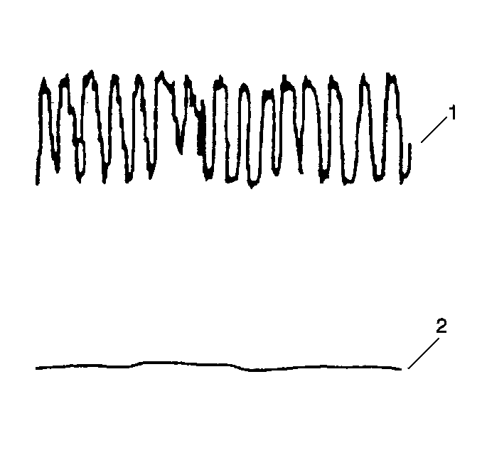
The control module monitors the post catalyst HO2S signal voltage in order to measure the oxygen storage capacity of the converter. A good catalytic converter is indicated when the post-catalyst HO2S signal voltage is relatively steady (2) compared to the pre-catalyst HO2S signal voltage (1).

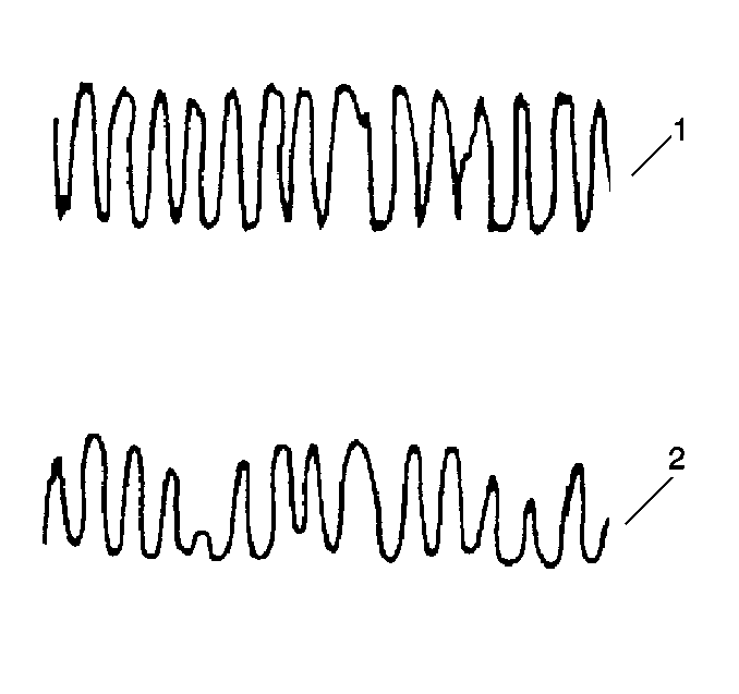
A malfunctioning catalytic converter is indicated when the post-catalyst HO2S signal voltage is more active (2), similar to the pre-catalyst HO2S signal voltage (1).
In addition to catalyst monitoring, the post catalyst HO2S has a limited role in fuel control.
Important: Do not use post-catalyst HO2S voltage activity in order to determine the efficiency of the TWC converter unless directed to do so by a diagnostic procedure.
The catalyst monitor on-board diagnostic tests can be effected by the following:
| • | A slightly degraded or marginal catalyst |
| • | Fuel containing high amounts of the following contaminants: |
| - | Sulfur |
| - | Silica |
| - | Lead |
| - | Phosphorus |
| • | Exhaust system leaks may cause the following : |
| - | Prevent a degraded or marginal TWC converter from failing a diagnostic test |
| - | Cause a normally functioning TWC converter to fail a diagnostic test |
| - | Prevent the diagnostic test from running |
| • | An aftermarket HO2S |
| • | An aftermarket catalytic converter |
Misfire Monitor Diagnostic Tests
When the engine is running and a cylinder misfires, the crankshaft slows down momentarily. The control module has the ability to detect this change in speed by monitoring the input signals from the following sensors:
| • | The crankshaft position (CKP) sensor |
| • | The camshaft position (CMP) sensor |
When the control module is running the misfire on-board diagnostic tests and a misfire is detected, the misfire counter stores or accumulates the position and the number of misfires. Two counters or accumulators are assigned to each of the cylinders. The counters are as follows:
| • | The current misfire counters--The current misfire counters store the number of misfires that have occurred in the last 200 engine cycles. When the control module detects an unacceptable amount of misfires stored in a current misfire counter, the misfire on-board diagnostic test fails and a misfire diagnostic trouble code (DTC) will set. |
| • | The history misfire counters--When a misfire DTC is set, the history misfire counters store the total number of misfires that have occurred every 200 engine cycles. |
Misfire Counters

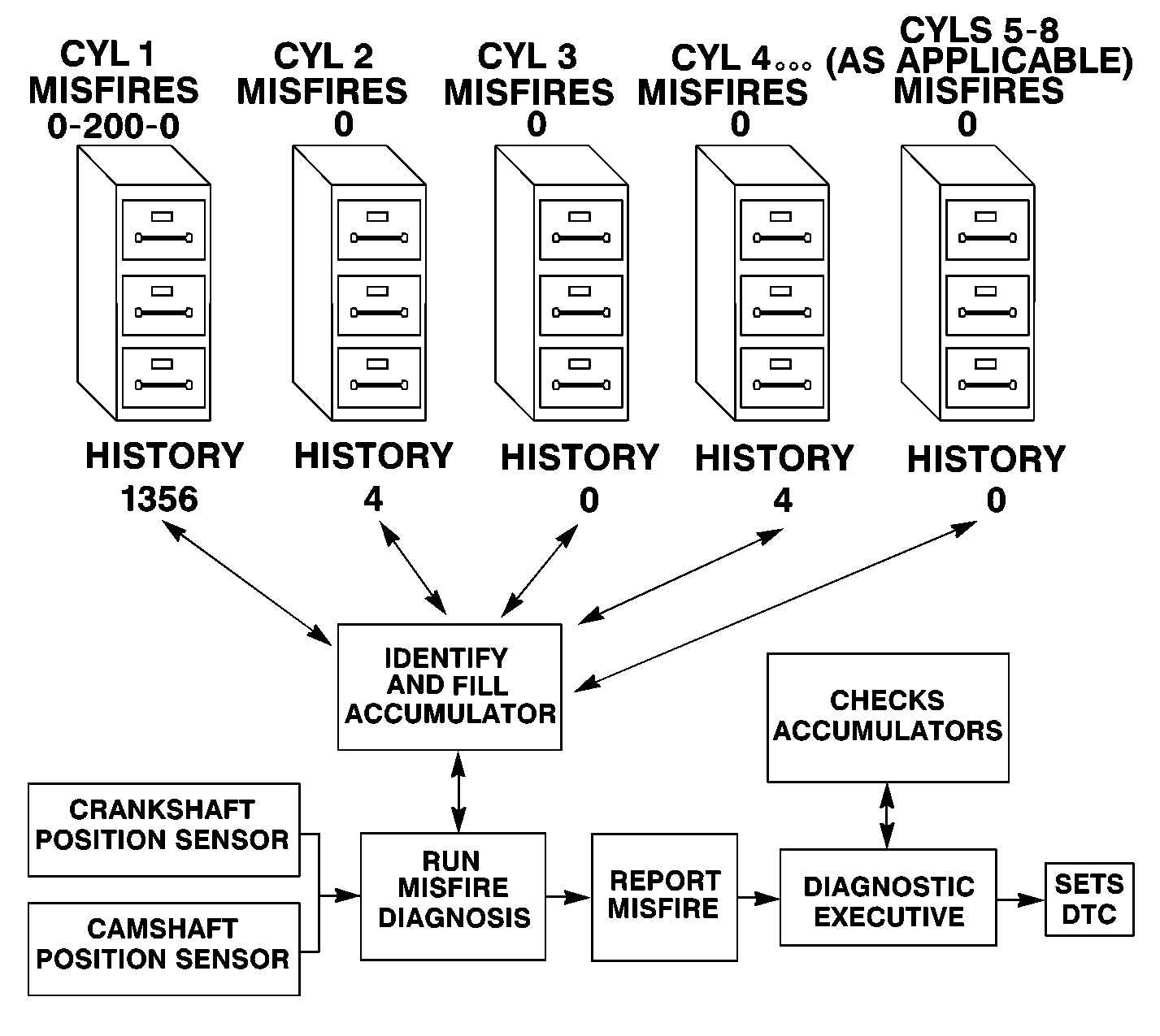
The misfire counters graphic illustrates how the misfire diagnosis and the diagnostic executive use the misfire counters or accumulators. When a misfire diagnostic test fails and reports to the diagnostic executive that a misfire condition exists, the diagnostic executive reviews all of the misfire counters in order to store the most current misfire information.
In the example illustrated by the misfire counters graphic, a misfire DTC has been set and the misfires are stored in more than one history misfire counter or accumulator. The cylinder number 1 history misfire and current misfire counters indicates more misfires than the other cylinders. The misfires stored in the cylinder number 2 and the cylinder number 4 history misfire counters or accumulators indicate the erratic rotation of the crankshaft caused by the misfire of number 1 cylinder. In this example, viewing the current misfire and history misfire counters indicate that a true misfire is present and the malfunction is located at cylinder number 1.
Use a scan tool in order to monitor the misfire counters data. Identify which cylinder or cylinders are misfiring. Inspect the systems and components common to the cylinders if multiple cylinders indicate a misfire is present.
Fuel Trim System Monitor Diagnostic Tests
The fuel trim monitor diagnostic tests monitor the fuel trim values. When the diagnostic tests indicate that the fuel trim system has reached the limits of fuel control at certain engine operating conditions, a fuel trim DTC will set.
Component Diagnostics
The component diagnostics are tests that monitor and evaluate the emission related input components and output components related to the control module. The control module tests the components, the components circuits, and the performance of these components.
