ENGINE OVERHEAT CONDITION ASSISTANCE IN DIAGNOSING

SUBJECT: ENGINE OVERHEAT
MODELS: 1988-91 C/K AND R/V TRUCKS WITH 5.7L (VIN CODE K) AND 7.4L (VIN CODE N) ENGINES
THIS BULLETIN CANCELS AND REPLACES GMC TRUCK SERVICE BULLETIN 91-6B-54, DATED JANUARY, 1991 TO CORRECT THE TEMPERATURES LISTED IN THE FIFTH PARAGRAPH OF THE FAN CLUTCH SECTION. ALL COPIES OF 91-6B-54 SHOULD BE DISCARDED.
The purpose of this bulletin is to provide assistance in diagnosing a possible engine overheat condition on 1988-91 C/K and R/V trucks equipped with 5.7L or 7.4L engines. The information contained herein has been taken from cases submitted to the Technical Assistance Center, and from engineering reviews on vehicles exhibiting engine overheat.
Included in this bulletin are copies of all previously published service bulletins which relate to 1988-90 C/K and R/V cooling systems. A review of these is recommended before proceeding.
When starting your diagnosis, it is very important that you first confirm at what temperature the engine is operating. Start by connecting a scan tool to the vehicles ALDL Connector and observe the engine coolant temperature. Compare this reading to the temperature gauge (if equipped) in the instrument panel cluster. Do they agree? If the gauge reading is significantly higher (more than 10 degrees), diagnose the gauge, sensor and related wiring first. If they agree, continue in your diagnosis of the engine cooling system. On vehicles equipped with a temperature indicator light (no gauges), verify the engine temperature when the temperature light turns on. The light is designed to turn on at 250 degrees F. If the light is turning on and the engine coolant temperature on the scan tool is displaying 245 degrees F or less, diagnose the temperature light, switch and related wiring first. If the engine coolant temperature is between 245 and 265 degrees F when the light comes on, continue with your diagnosis of the cooling system. On C/K models equipped with gauges, verify the engine temperature when the check gauges light turns on. The light is designed to turn on at 245 degrees F. If the light is turning on before 245 degrees F, diagnose the check gauges light first. See GMC Truck Service Bulletin number 88-T-86 (Corporate Number 866204) for additional information.
When diagnosing a complaint of engine overheat it is very important to find out exactly when the overheat occurs. Most engine overheats fall into one of the following categories: overheats when idling, or overheats when operating under a heavy load or towing.
If the overheat occurs when idling, the following information should be obtained before starting your diagnosis.
1. What is the coolant temperature when the engine first begins to idle? 2. How long (minutes) does it take from the time the engine starts to idle for the overheat to occur? 3. Is the transmission in drive/reverse, or is it in park/neutral during this period of time? 4. If equipped with air conditioning, is the A/C in use when the overheat occurs? 5. What is the approximate ambient temperature outside the vehicle at the time? 6. How was the vehicle being driven before idling: highway, mountains, city, offroad, etc.?
If the overheat occurs when under heavy loads or towing, the following information should be obtained before starting your diagnosis.
1. At what road speed is the vehicle being driven when the overheat occurs? 2. If equipped with air conditioning, is the A/C in use when the overheat occurs? 3. What is the approximate ambient temperature outside the vehicle at the time? 4. Where is the vehicle being driven (highway, mountains, off-road)? 5. What is the weight of the load or trailer? 6. What is the Gross Vehicle Weight Rating (GVWR) and the Gross Combination Weight Rating (GCWR) of the vehicle? This is needed to determine if the vehicle is being overloaded.
The following is a list of cooling system components as well as what you should be looking for when conducting your diagnosis.
WATER PUMP BY-PASS
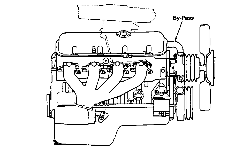
On the 7.4L engine there is a short heater hose between the front of the intake manifold and the water pump (Figure 1). The function of this hose is to allow coolant to circulate within the engine during warm-up while the thermostat is closed. Circulating the coolant allows for a more rapid and even warm-up of the engine. After the thermostat opens some coolant flow will continue through this by-pass.
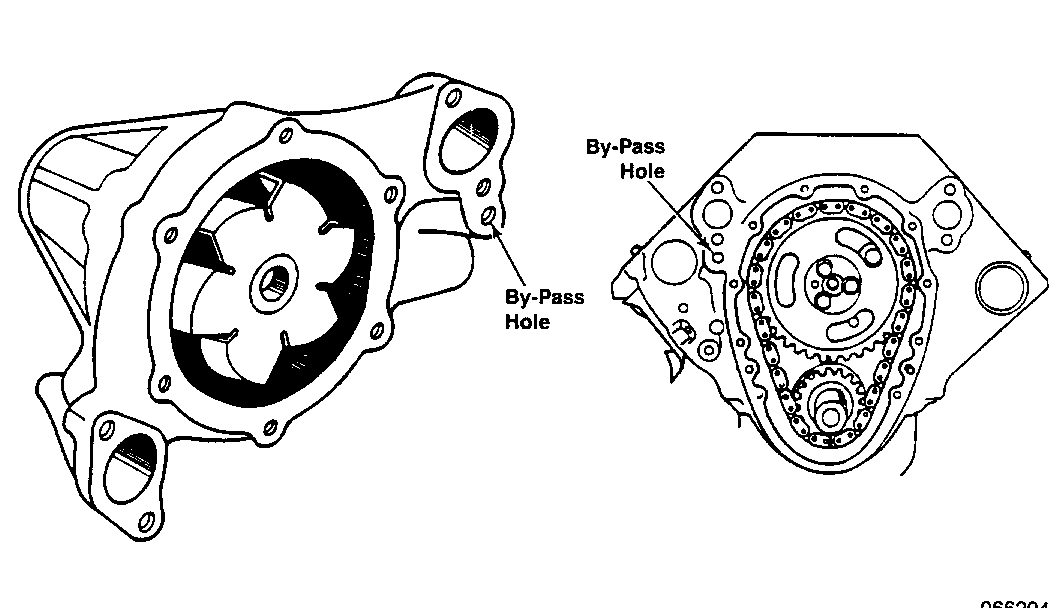
On the 5.7L engine the by-pass is a passageway that goes from the right side of the water pump (Figure 2) into and up through the block and into the right cylinder head. It functions in the same manner as the 7.4L.
If this by-pass were to become plugged, the coolant would not circulate during warm-up. As a result, there may be some areas of the engine that get warmer than others. If the instrument panel temperature gauge sensor is located in one of these areas, the gauge would indicate a warmer temperature. This reading would not reflect the overall engine temperature. Once the thermostat opens, the engine temperature will begin to even out. However, even with the thermostat open, there will be a reduced coolant flow back to the water pump. This reduced flow may result in higher over-all coolant temperatures.
Verification of by-pass operation can be performed on the 7.4L engine by removing the by-pass hose and checking for coolant flow or obstructions.
Verification of by-pass operation can be performed on the 5.7L only by removing the water pump from the engine. With the water pump removed, check for an obstruction in the passageway in both the engine block and pump.
ELECTRIC FAN
Electric fan is standard on the 7.4L with air conditioning. Verify that the electric fan is operating properly. The fan should engage at approximately 225 degrees F Also verify that the fan is turning in the right direction. When viewed through the grille, the fan should be turning counter-clockwise.
FAN
Check the fan for damaged blades. Bent or missing blades can cause poor cooling system performance as well as vibrations. Verify that the fan is correct for the engine and application. See the service parts book (Group 1.064) for correct usage.
FAN CLUTCH
Verify that the fan clutch is correct for the engine and application. The clutch has a two letter code stamped on the housing, usually on or near the outside edge. The service parts book (Group 1.050) references the codes in relation to the service part numbers and application.
DIAGNOSIS
With the engine off, rotate the fan by hand. It should have some drag, but it should turn smoothly. If it does not turn smoothly, does not turn at all, or exhibits extreme bearing looseness, it should be replaced. When the engine has been off for a considerable period of time (greater than eight hours), the fan clutch may be engaged when the engine is first started. The clutch will remain engaged until the silicone fluid inside can be redistributed to its normal disengaged operating condition. The fan clutch should disengage after not more than five minutes if the engine speed is kept about 2,000 RPM. A reduction in fan noise will be noticeable when the fan clutch disengages.
To verify the engagement and disengagement of the fan clutch in relation to engine temperature, connect a scan tool to the vehicle's ALDL Connector and observe the engine coolant temperature. Coolant temperature should be below 140 degrees F before the start of the test. Start the engine, let idle and observe the coolant temperature. The temperature should rise at a steady rate until the thermostat opens (about 195 degrees F). When the thermostat opens, the coolant temperature may momentarily drop a few degrees, or stay constant for a minute or two. This should be considered as normal. At this point it will be necessary to road test the vehicle in order to get an appropriate amount of air flow across the radiator.
Drive the vehicle at a steady speed and continue to monitor coolant temperature until approximately 225 degrees F is obtained. At this temperature you should be able to hear an increase in fan noise as the clutch engages. If the fan clutch does not engage, continue driving and monitoring the coolant temperature until 235 degrees F is obtained. If the fan clutch has still not engaged, the clutch should be replaced.
NOTE: If the ambient temperature during the road test is less than 70 degrees F, it may not be possible to obtain the coolant temperature of 225 degrees F required for the clutch test. If this condition is encountered it may be necessary to partially obstruct (about 50%) the air flow across the radia- tor or AIC condenser with a piece of cardboard. Remove the cardboard upon completion of the clutch test.
When the fan clutch engages, the engine coolant temperature will decrease until a temperature of approximately 195 degrees F. At this point the fan clutch should disengage resulting in a decrease in fan noise. If the fan clutch does not disengage, continue driving and monitoring coolant tempera- ture until 190 degrees F is reached. If the fan clutch has still not disengaged, the clutch should be replaced.
RADIATOR
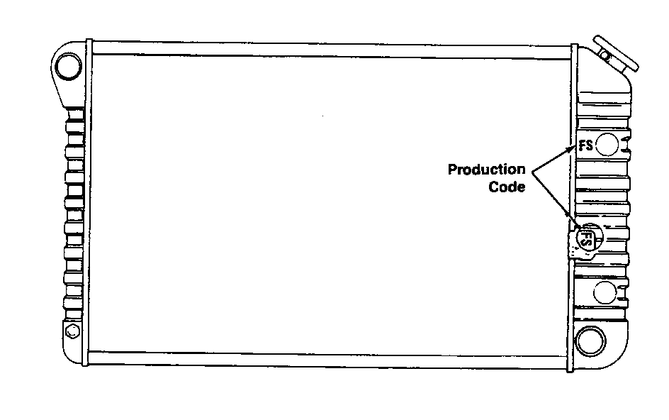
Verify that the radiator is correct for the engine and application. There is a two lefter radiator production code located on the right radiator tank (Figure 3). The service parts books (Group 1.219) have a chart to convert these codes into service part numbers and then to applications.
DIAGNOSIS
Check for visible signs of coolant leakage. Often when a leak is present, there will be a slight build-up of a powdery residue in and around the leak. Check for distortion of the radiator cooling fins on both sides of the radiator. To check both sides thoroughly may require the removal of the radiator from the vehicle. Bent or damaged fins reduce the cooling system performance.
Check for air flow restrictions within the radiator cooling fins. Often when vehicles are used in dusty or off-road conditions, the cooling fins become plugged with dirt, grass, insects and other types of debris. If 25% of the radiator cooling fins are restricted, then the radiator is only operating at 75% efficiency.
Check the condition of the radiator on the inside. As vehicles start to accumulate miles, the possibility of the radiator core becoming plugged increases. Having the radiator boiled out doesn't always correct this condition. If the radiator is suspected as being plugged, remove it from the vehicle, have the tanks removed from the core, and have the core rodded out.
RADIATOR CAP
Check that the radiator cap is correct for the application. Check the operation of the cap by pressure testing with cooling system pressure tester J24460-01. Replace cap if 15 psi cannot be maintained.
CAUTION:
THE RADIATOR CAP SHOULD BE REMOVED FROM A COOL ENGINE ONLY. IF THE RADIATOR IS REMOVED FROM A HOT COOLING SYSTEM, SERIOUS PERSONAL INJURY MAY RESULT.
AIR CONDITIONING CONDENSER
With the engine off, check for distortion of the condenser cooling fins on both sides of the condenser. To check the side closest to the radiator, remove the upper fan shroud, and tilt the radiator towards the rear of the vehicle. When performing this procedure, check for air flow restrictions within the condenser cooling fins. Like the radiator fins, the condenser fins can also become plugged by debris. This not only affects the air flow going to the radiator, but also reduces the performance of the air conditioning system. If possible, clean both the radiator and condenser cooling fins with pressurized tap water (garden hose).
AIR CONDITIONING SYSTEM
Check that the air conditioning system is not overcharged. An overcharged system will cause excessively high system pressures. These higher pressures relate to higher temperatures in the condenser. As a result, the air flow moving across the condenser to the radiator is warmer than normal. This warmer condition reduces the ability of the radiator to dissipate its own heat.
THERMOSTAT
Check that the thermostat is operating correctly. The thermostat should open when the engine reaches approximately 195 degrees F. To verify this, connect a scan tool to the vehicle's ALDL Connector and monitor coolant temperature. The coolant temperature should be below 140 degrees F before the start of this test. Start the engine, let idle and observe the coolant temperature. The temperature should rise at a steady rate until the thermostat opens (about 195 degrees F). At this point the coolant temperature may momentarily drop a few degrees, or stay constant for a minute or two. If the thermostat opens at a temperature lower than 190 degrees F or higher than 200 degrees F, it should be replaced.
HOSES
Check that the upper and lower radiator hoses as well as all heater hoses are not collapsed or kinked. Such restrictions can interrupt or reduce the flow of coolant.
COOLANT
Today's vehicles are designed to operate with a 44/56 solution of antifreeze and water for optimum cooling system performance. This gives freeze pro- tection to -20 degrees F in colder climates a 50/50 solution is recommended for freeze protection to -34 degrees F.
These solutions give the correct cooling system balance of freeze protection, heat dissipation and corrosion protection.
When cooling systems are drained for any reason it is important that the correct concentration of antifreeze be maintained. Increasing or decreasing the antifreeze concentration from the desired mix can have undesirable effects on the system.
Listed here are some useful facts concerning antifreeze concentrations:
o GM coolant specification 6038-M (P/N 1052103) is recommended for all light and medium duty trucks with gasoline or diesel engines.
o A 50/50 antifreeze mix increases cooling capacity about 15% over clear water.
o Maximum freeze protection is obtained at about 69% antifreeze. Higher concentrations actually raise the freeze point.
o The freeze point of 100% antifreeze is about -8 degrees F.
o Engine damage from freezing due to very high concentrations of antifreeze is not likely for two reasons.
1. High concentration solutions do not freeze to a solid, but become a heavy slush.
2. High concentrations of antifreeze contract rather than expand at their freezing point.
COOLANT LEVEL
Check the overflow reservoir to see that the radiator and cooling system are filled to the proper level. If the reservoir level is low or is completely empty, check it for leaks.
BELTS
Check that the serpentine belt is routed correctly around all the pulleys. Incorrect routing of the belt may result in the water pump turning in the wrong direction. An illustration of the correct belt routing for the application is on a label located on the fan shroud.
WATER PUMP
Check to see if the water pump is actually moving the coolant. This can be done by observing the coolant flow back to the radiator, by way of the heater hose, through the radiator cap opening. This check can only be made on a warmed-up engine (thermostat open). If there is no coolant being returned to the radiator, the water pump impeller may be slipping on the shaft.
CAUTION:
THE RADIATOR CAP SHOULD BE REMOVED FROM A COOL ENGINE ONLY. IF THE RADIATOR IS REMOVED FROM A HOT COOLING SYSTEM, SERIOUS PERSONAL INJURY MAY RESULT.
If the complaint is for an overheat condition on initial start of 4.3L, 5.OL or 5.7L engines, see GMC
Truck Service Bulletin (Corporate # 836001R). This bulletin describes the removal of a casting dam in the water pump.
FAN SHROUD
Check that the fan shroud is correct for the application and that it is not damaged (pieces missing). If the fan, fan clutch and shroud are correct for the application, the fan blades will be positioned partially (half way) inside the fan shroud and partially (half way) outside the fan shroud. In an incorrect assembly, the fan blades will either be too far inside or outside the fan shroud. When the blades are not positioned correctly, the fan will not be able to draw the required amount of air across the radiator, possibly resulting in an overheat at idle.
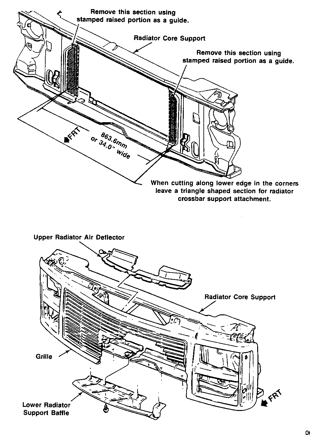
RADIATOR CORE SUPPORT- C/K Models ---------------------------------- On models equipped with the 7.4L engine, verify that the radiator core support has the correct opening dimensions. See GMC Truck service bulletin #88-T-143 (Corporate Number 866205).
BAFFLES AND DEFLECTORS - C/K Models ------------------------------------ On models equipped with the 7.4L engine, verify that the lower radiator support baffle has been installed (Figure 4). For additional information see GMC Truck service bulletin # 88-T-143 (Corporate Number 866205). Also verify that the upper radiator air deflector has been installed (Figure 4).
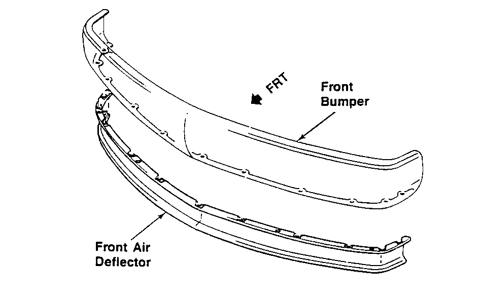
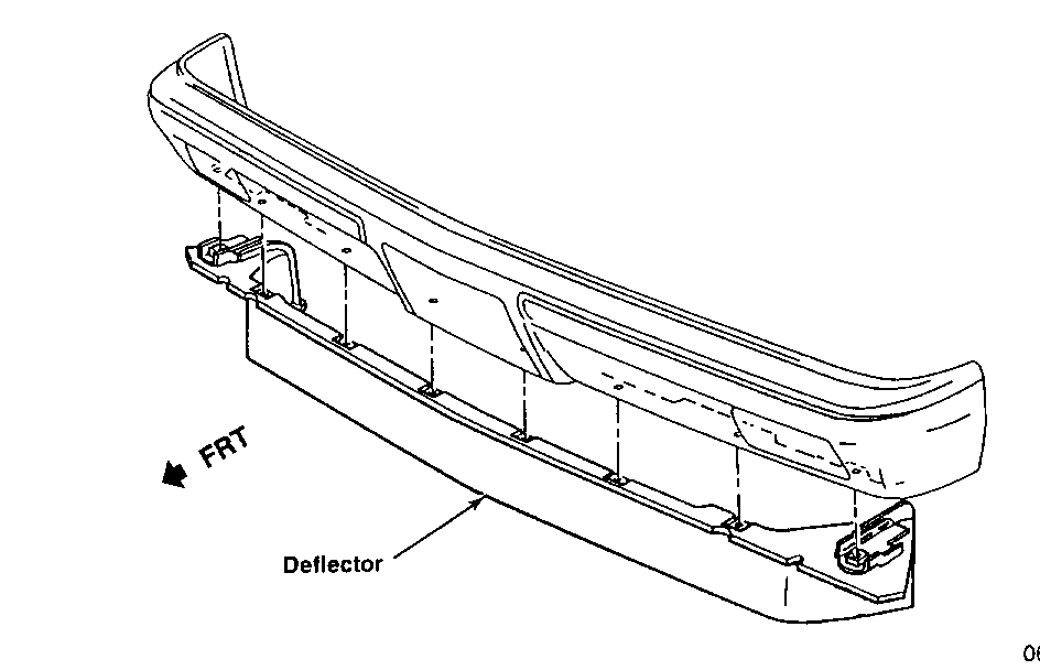
On models equipped with the 5.7L engine, verify that the front bumper air deflector has been installed (Figure 5).
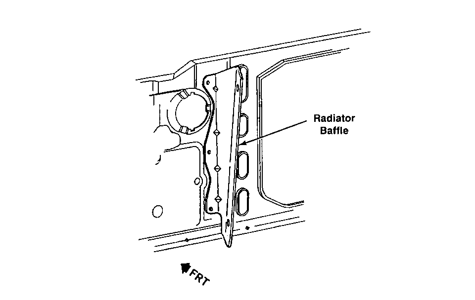
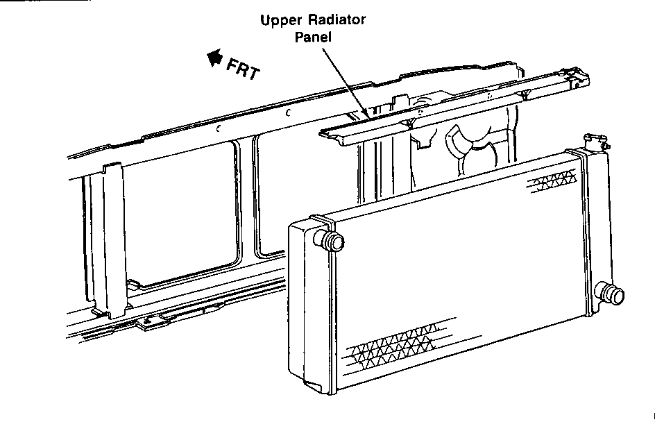
BAFFLES, DEFLECTORS, PANELS and SEALS - R/V models ---------------------------------------------------- On R/V models equipped with the 7.4L engine, verify that the radiator baffle has been installed (Figure 6). Also verify that the upper radiator panel has been installed (Figure 7).
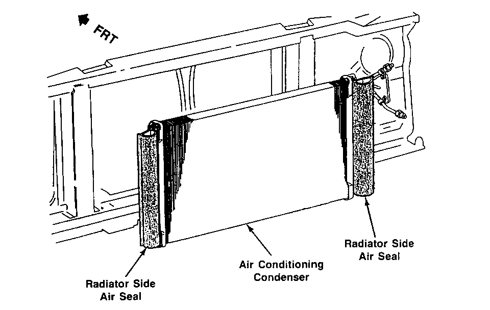
On R/V models equipped with the 5.7L engine, verify that the front bumper air deflector has been installed (Figure 8). On models with air conditioning, verify that both left and right radiator seals have been installed (Figure 9).
AFTERMARKET ACCESSORIES
Verify that there are no aftermarket transmission oil coolers or other aftermarket accessories mounted in front of the radiator or condenser. Accessories mounted in this area reduce or alter air flow required for proper cooling. Relocate all such aftermarket accessories to an area where air flow to the radiator or condenser will not be affected.
General Motors bulletins are intended for use by professional technicians, not a "do-it-yourselfer". They are written to inform those technicians of conditions that may occur on some vehicles, or to provide information that could assist in the proper service of a vehicle. Properly trained technicians have the equipment, tools, safety instructions and know-how to do a job properly and safely. If a condition is described, do not assume that the bulletin applies to your vehicle, or that your vehicle will have that condition. See a General Motors dealer servicing your brand of General Motors vehicle for information on whether your vehicle may benefit from the information.
