DTC P0327 Knock Sensor (KS) Circuit with L19 or L29
Circuit Description
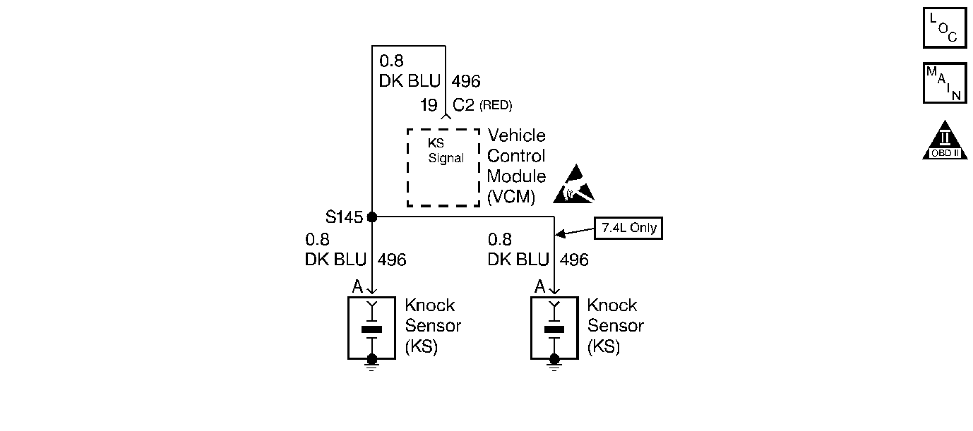
The VCM uses the Knock Sensors (KS) in order to detect engine detonation. This allows the VCM to retard the Ignition Control (IC) spark timing based on the KS signal which the VCM receives. The circuitry within the knock sensor pulls down the VCM-supplied 5 volt signal, so that under a no knock condition the signal on the KS circuit measures about 1.3 volts. The knock sensors produce an AC signal that rides on the 1.3 volts DC. The amplitude and frequency of the AC signal are dependent upon the amount of the knock being experienced.
The VCM determines whether the knock is occurring by comparing the signal level on the KS circuit with a voltage level on the noise channel. The noise channel allows the VCM to reject any false knock signal by indicating the amount of normal engine mechanical noise present. The normal engine noise varies depending on the engine speed and load. When the VCM determines that an abnormally high noise channel voltage level is being experienced, a DTC P0326 sets. This DTC is a type B DTC.
Conditions for Setting the DTC
Knock Sensor Update Test
| • | The timing retard is no more than 0 degrees. |
| • | System voltage is greater than 10 volts but no more than 17.1 volts |
| • | The Engine Coolant Temperature sensor is greater than 60°C (140°F) |
| • | Engine run time is greater than 2 minutes |
| • | Engine speed is between 500 RPM and 900 RPM for the 5.0L,5.7L |
| • | Engine speed is between 525 RPM and 750 RPM for the 7.4L |
SNEF Stuck low Test 5.0L,5.7L
| • | Engine run time is greater than or equal to 120 seconds |
| • | System voltage is greater than or equal to 10 v but less than 17.1 v |
Active Noise Channel Test
| • | No ECT DTCs set |
| • | No TP sensor DTCs set |
| • | The Knock Sensor update test is complete |
| • | The ECT is at least 60°C (140°F) |
| • | The engine speed is greater than or equal to 2000 RPM and less than 10000 RPM |
| • | The throttle angle is at least 5.8% |
| • | The engine has been running for at least 2 minutes |
| • | The system voltage is greater than 10 volts but no more than 17.1 volts |
| • | The timing retard is no more than 0 degrees. |
Action Taken When DTC Sets
| • | The VCM will not illuminate the MIL |
| • | The VCM will store the conditions which were present when the DTC set as a Fail Records data only. This information will not store as Freeze Frame Data. |
| • | The VCM will use a calculated spark retard value in order to minimize the knock during the conditions when the knock is most likely to occur. The calculated value will vary based on the engine speed and load. |
Conditions for Clearing the MIL/DTC
| • | A history DTC will clear after 40 consecutive warm-up cycles have occurred without a fault |
| • | The scan tool Clear Info function or disconnecting the VCM battery feed can clear the DTC |
Diagnostic Aids
Check for the following conditions:
| • | A poor connection at the VCM -- Inspect the knock sensor and the VCM connectors for the following items: |
| - | Backed out terminals |
| - | Broken locks |
| - | Improperly formed or damaged terminals |
| • | A misrouted harness -- Inspect the knock sensor harness in order to ensure that it is not routed too close to high voltage wires such as spark plug leads. |
Notice: Use the correct fastener in the correct location. Replacement fasteners must be the correct part number for that application. Fasteners requiring replacement or fasteners requiring the use of thread locking compound or sealant are identified in the service procedure. Do not use paints, lubricants, or corrosion inhibitors on fasteners or fastener joint surfaces unless specified. These coatings affect fastener torque and joint clamping force and may damage the fastener. Use the correct tightening sequence and specifications when installing fasteners in order to avoid damage to parts and systems.
| • | Improper knock sensor torque specification. Torque the knock sensor to 19 N·m (14 lbs ft). |
Review the Failure Records vehicle mileage since the diagnostic test last failed in order to help determine how often the conditions that caused the DTC to set occur. This may assist in diagnosing the condition.
Test Description
The numbers below refer to the step numbers on the diagnostic table.
-
Ensures that the fault is present.
-
Ensures that the knock sensor is capable of detecting detonation.
Step | Action | Value(s) | Yes | No |
|---|---|---|---|---|
1 |
Important: Before clearing the DTCs use the scan tool in order to record the Freeze Frame and Failure Records for reference because the data will be lost when the Clear Info function is used. Was the Powertrain On-Board Diagnostic (OBD) System Check performed? | -- | ||
Does the scan tool indicate the DTC P0327 failed this ignition? | -- | |||
3 |
Does the scan tool indicate the DTC P0327 Failed This Ign? | -- | Go to Diagnostic Aids | |
4 |
Is the voltage approximately at the specified value? | 5V | ||
5 | Measure the resistance of each KS sensor by connecting the DVM between the KS sensor terminal and the engine block. Is the resistance of each KS sensor near the specified value? | 8K ohms | ||
Is any signal indicated on the DVM while tapping on the engine lift bracket? | -- | |||
7 |
Was a problem found? | -- | ||
8 |
Was a problem found? | -- | ||
9 | Replace the Knock Sensor. Refer to Knock Sensor Replacement for the 5.0L, 5.7L, 7.4L. Is action complete? | -- | -- | |
10 |
Was a problem found? | -- | ||
11 |
Was a problem found? | -- | ||
12 |
Does the scan tool indicate DTC P0327 Failed This Ign? | -- | ||
13 | Replace the VCM. Important: If the VCM is faulty, reprogram the VCM. Refer to VCM Replacement/Programming . Is the action complete? | -- | -- | |
14 |
Does the scan tool indicate that this diagnostic ran and passed? | -- | ||
15 | Using the scan tool, select the Capture Info and the Review Info. Are any DTCs displayed that have not been diagnosed? | -- | Go to The Applicable DTC Table | System OK |
DTC P0327 Knock Sensor (KS) Circuit with L 30 or L 31
Circuit Description
The VCM uses the Knock Sensors (KS) in order to detect engine detonation. This allows the VCM to retard the Ignition Control (IC) spark timing based on the KS signal which the VCM receives. The circuitry within the knock sensor pulls down the VCM-supplied 5 volt signal, so that under a no knock condition the signal on the KS circuit measures about 1.3 volts. The knock sensors produce an AC signal that rides on the 1.3 volts DC. The amplitude and frequency of the AC signal are dependent upon the amount of the knock being experienced.
The VCM determines whether the knock is occurring by comparing the signal level on the KS circuit with a voltage level on the noise channel. The noise channel allows the VCM to reject any false knock signal by indicating the amount of normal engine mechanical noise present. The normal engine noise varies depending on the engine speed and load. When the VCM determines that an abnormally high noise channel voltage level is being experienced, a DTC P0326 sets. This DTC is a type B DTC.
Conditions for Setting the DTC
Knock Sensor Update Test
| • | The timing retard is no more than 0 degrees. |
| • | System voltage is greater than 10 volts but no more than 17.1 volts |
| • | The Engine Coolant Temperature sensor is greater than 60°C (140°F) |
| • | Engine run time is greater than 2 minutes |
| • | Engine speed is between 500 RPM and 900 RPM |
Active Noise Channel Test
| • | No ECT DTCs set |
| • | No TP sensor DTCs set |
| • | The Knock Sensor update test is complete |
| • | The ECT is at least 60°C (140°F) |
| • | The engine speed is between 2000 RPM and 3000 RPM |
| • | The throttle angle is at least 5.8% |
| • | The engine has been running for at least 2 minutes |
| • | The system voltage is greater than 10 volts but no more than 17.1 volts |
| • | The timing retard is no more than 0 degrees. |
| • | The VCM is monitoring a ESC noise channel voltage level is below 0.5 volt |
Action Taken When DTC Sets
| • | The VCM will not illuminate the MIL |
| • | The VCM will store the conditions which were present when the DTC set as a Fail Records data only. This information will not store as Freeze Frame Data. |
| • | The VCM will use a calculated spark retard value in order to minimize the knock during the conditions when the knock is most likely to occur. The calculated value will vary based on the engine speed and load. |
Conditions for Clearing the MIL/DTC
| • | A history DTC will clear after 40 consecutive warm-up cycles have occurred without a fault |
| • | The scan tool Clear Info function or disconnecting the VCM battery feed can clear the DTC |
Diagnostic Aids
Check for the following conditions:
| • | A poor connection at the VCM -- Inspect the knock sensor and the VCM connectors for the following items: |
| - | Backed out terminals |
| - | Broken locks |
| - | Improperly formed or damaged terminals |
| • | A misrouted harness -- Inspect the knock sensor harness in order to ensure that it is not routed too close to high voltage wires such as spark plug leads. |
Notice: Use the correct fastener in the correct location. Replacement fasteners must be the correct part number for that application. Fasteners requiring replacement or fasteners requiring the use of thread locking compound or sealant are identified in the service procedure. Do not use paints, lubricants, or corrosion inhibitors on fasteners or fastener joint surfaces unless specified. These coatings affect fastener torque and joint clamping force and may damage the fastener. Use the correct tightening sequence and specifications when installing fasteners in order to avoid damage to parts and systems.
| • | Improper knock sensor torque specification. Torque the knock sensor to 19 N·m (14 lbs ft). |
Review the Failure Records vehicle mileage since the diagnostic test last failed in order to help determine how often the conditions that caused the DTC to set occur. This may assist in diagnosing the condition.
Test Description
The numbers below refer to the step numbers on the diagnostic table.
-
Ensures that the fault is present.
-
Ensures that the knock sensor is capable of detecting detonation.
Step | Action | Value(s) | Yes | No |
|---|---|---|---|---|
1 |
Important: Before clearing the DTCs use the scan tool in order to record the Freeze Frame and Failure Records for reference because the data will be lost when the Clear Info function is used. Was the Powertrain On-Board Diagnostic (OBD) System Check performed? | -- | ||
Does the scan tool indicate the DTC P0327 failed this ign? | -- | |||
3 |
Does the scan tool indicate the DTC P0327 failed this ign? | -- | Go to Diagnostic Aids | |
4 |
Is the voltage approximately at the specified value? | 5 V | ||
5 | Measure the resistance of each KS sensor by connecting the DVM between the KS sensor terminal and the engine block. Is the resistance of each KS sensor near the specified value? | 100K ohms | ||
Is any signal indicated on the DVM while tapping on the engine lift bracket? | -- | |||
7 |
Was a problem found? | -- | ||
8 |
Was a problem found? | -- | ||
9 | Replace the Knock Sensor. Refer to Knock Sensor Replacement for the 5.0L, 5.7L, 7.4L. Is action complete? | -- | -- | |
10 |
Was a problem found? | -- | ||
11 |
Was a problem found? | -- | ||
12 |
Does the scan tool indicate DTC P0327 Failed This Ign? | -- | ||
13 | Replace the VCM. Important: If the VCM is faulty, reprogram the VCM. Refer to VCM Replacement/Programming . Is the action complete? | -- | -- | |
14 |
Does the scan tool indicate that this diagnostic ran and passed? | -- | ||
15 | Using the scan tool, select the Capture Info and the Review Info. Are any DTCs displayed that have not been diagnosed? | -- | Go to The Applicable DTC Table | System OK |
