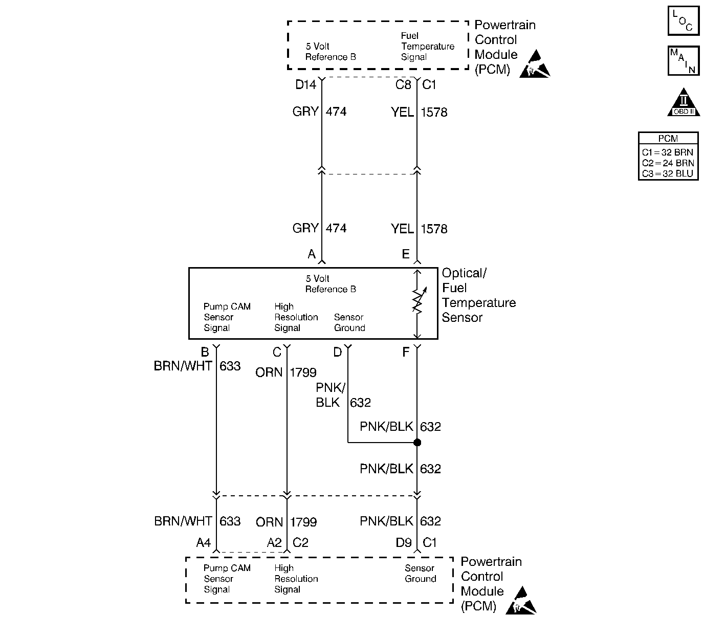
Circuit Description
The fuel temperature sensor is a thermistor that controls signal voltage to the PCM. When the fuel is cold, the sensor resistance is high, therefore the PCM will see high signal voltage. As fuel warms, sensor resistance becomes less and voltage drops. The fuel temperature sensor is integrated with the optical sensor.
Conditions for Running the DTC
| • | The PCM performs this DTC diagnostic continuously. |
| • | The ignition switch in the ON position. |
Conditions for Setting the DTC
| • | The fuel temperature is more than or equal to 102°C (215°F). |
| • | All of the diagnostic set conditions met for 2 seconds. |
Action Taken When the DTC Sets
| • | The PCM illuminates the malfunction indicator lamp (MIL) on the second consecutive drive trip that the diagnostic runs and fails. |
| • | The PCM records the operating conditions at the time the diagnostic fails. The first time the diagnostic fails, the Failure Records will store this information. If the diagnostic reports a failure on the second consecutive drive trip, the Freeze Frame records the operating conditions at the time of failure and updates the Failure Records. |
Conditions for Clearing the MIL/DTC
| • | The PCM will turn the MIL off after 3 consecutive trips without a fault condition. |
| • | A history DTC clears after 40 consecutive warm-up cycles, if this or any other emission related diagnostic does not report any failures. |
| • | The scan tool Clear Info function was used. |
Diagnostic Aids
A scan tool reads fuel temperature in degrees centigrade.
An intermittent may be caused by any of the following conditions:
| • | A poor connection |
| • | Rubbed through wire insulation |
| • | A broken wire inside the insulation |
Thoroughly check any circuitry that is suspected of causing the intermittent complaint. Refer to Intermittents and Poor Connections Diagnosis in Wiring Systems.
If a repair is necessary, refer to Wiring Repairs or Connector Repairs in Wiring Systems.
Test Description
Number(s) below refer to the step number(s) on the Diagnostic Table.
-
This step determines if DTC P0182 is a hard failure or an intermittent condition.
-
This test will determine if signal circuit is shorted to ground.
Step | Action | Value(s) | Yes | No |
|---|---|---|---|---|
1 |
Important: Before clearing the DTCs, use the scan tool Capture Info to save the Freeze Frame and Failure Records for reference. The control module's data is deleted once the Clear Info function is used. Did you perform the Powertrain On-Board Diagnostic (OBD) System Check? | -- | ||
Is the Fuel Temp greater than the specified value? | 102°C (215°F) | |||
Is the Fuel Temp less than or equal to the specified value? | 17°C ( 63°F) | |||
4 |
Is the resistance at the specified value? | ∞ | ||
5 | The DTC is intermittent. If no additional DTCs are stored, refer to Diagnostic Aids. If additional DTCs were stored, refer to the applicable DTC table(s) first. Are additional DTC(s) stored? | -- | Go to the Applicable DTC Table | Go to Diagnostic Aids |
6 | Repair the short to ground in the Fuel Temp signal circuit. Is the action complete? | -- | -- | |
7 | Replace the fuel injection pump. Refer to Fuel Injection Pump Replacement . Important: The new injection pump must be timed. Refer to Fuel Injection Pump Timing Adjustment . Is the action complete? | -- | -- | |
8 | Replace the PCM. Important: The new PCM must be programmed. Refer to Powertrain Control Module Replacement/Programming . Is the action complete? | -- | -- | |
9 |
Does the scan tool indicate the diagnostic Passed? | -- | ||
10 | Does the scan tool display any additional undiagnosed DTCs? | -- | Go to the Applicable DTC Table | System OK |
