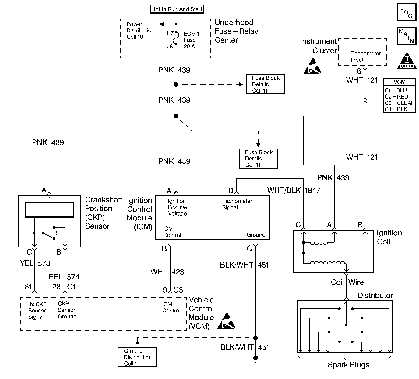
Circuit Description
This system includes the Distributor, the ignition coil, the ignition control module, the secondary wires, spark plugs, the VCM and the crank sensor. The ignition system is controlled by the Vehicle Control Module (VCM). The VCM monitors the information from various engine sensors, computes the desired spark timing and controls the dwell and firing of the ignition coil via an (IC) line to the ignition control module.
Diagnostic Aids
Check the following:
The IC control circuit for an intermittent short to ground.
Check the following when the distributor rotor does not rotate, while engine is cranking:
| • | A broken distributor drive shaft |
| • | A worn distributor drive gear or camshaft timing chain and gears |
An intermittent may be cause by a poor connection, rubbed through wire insulation, or a broken wire inside the insulation. Thoroughly check any circuity that is suspected of causing the intermittent complaint for the following conditions:
| • | Backed out terminals |
| • | Improper mating |
| • | Broken locks |
| • | Improperly formed or damaged terminals |
| • | Poor terminal to wire connections |
| • | Physical damage to the wiring harness |
| • | Corrosion |
| • | Moisture in the connector |
Test Description
The numbers below refer to the step numbers in the diagnostic table.
The battery should be fully charged prior to any tests.
-
Perform the OBD system check before proceeding unless it was already performed.
-
Checks for proper output from the enhanced ignition system. The spark tester requires a minimum of 25,000 volts to operate. This check can be used in case of an ignition miss, because the system may provide enough voltage to run the engine but not enough to operate a spark plug under heavy load.
-
This test separates the distributor cap, rotor and ignition wires from the ignition coil in order to help identify a secondary ignition system problem.
-
This test checks the ignition control module, connections, and wiring.
-
This test begins to determine if the VCM is providing a signal to the ignition control module. If the VCM is not providing a signal to the ignition control module, the problem exists between the ignition control module and the VCM.
-
This test checks for a basic engine mechanical problem.
Step | Action | Value(s) | Yes | No | ||||||||
|---|---|---|---|---|---|---|---|---|---|---|---|---|
|
Important: Before clearing the DTCs, use the scan tool Capture Info to save the Freeze Frame and Failure Records for reference. The control module's data is deleted once the clear info function is used. Did you perform the Powertrain On-Board Diagnostic (OBD) System Check? | -- | |||||||||||
Is adequate spark present? | -- | Go to Symptoms | ||||||||||
Is adequate spark present? | -- | |||||||||||
4 | Measure the coil wire resistance using a J 39200 DMM. The resistance should be approximately the specified value. Is the resistance within the specified value? | 1000 ohms/inch | ||||||||||
Is the test lamp flashing while cranking the engine? | -- | |||||||||||
6 |
Is the test lamp ON? | -- | ||||||||||
7 | Probe the ignition coil harness connector terminal B with a test lamp connected to B+. Is the test lamp ON? | -- | ||||||||||
8 |
Does the voltage measure above the specified value? | 10.0 V | ||||||||||
9 |
Is the circuit open? | -- | ||||||||||
10 |
Does the voltage measure above the specified value? | 10.0 V | ||||||||||
11 | Probe the ignition control module harness connector terminal C with a test lamp connected to B+. Is the test lamp ON? | -- | ||||||||||
Is the voltage between the specified values? | 1.0-4.0 V | |||||||||||
13 |
Are any of these conditions present? | -- | ||||||||||
Did the distributor rotor turn? | -- | Go to Symptoms | ||||||||||
15 |
Is the circuit open? | -- | ||||||||||
16 | Probe the ignition control (IC) circuit at the VCM C3 connector with a test lamp connected to B+. Is the test lamp ON? | -- | ||||||||||
17 |
Is the test lamp ON? | -- | ||||||||||
18 | Check for an open or shorted to ground ignition positive voltage circuit at terminal A of the ignition coil. Repair as necessary. Refer to Wiring Repairs in Wiring Systems. Is the action complete? | -- | -- | |||||||||
19 | Check for an open or shorted to ground ignition positive voltage circuit at terminal A of the ignition control module. Repair as necessary. Refer to Wiring Repairs in Wiring Systems. Is the action complete? | -- | -- | |||||||||
20 | Check for a poor ignition control module connection. Did you find a problem? | -- | ||||||||||
21 | Check for a poor coil connection . Did you find a problem? | -- | ||||||||||
22 | Check for a poor VCM connection. Did you find a problem? | -- | ||||||||||
23 | Repair the open ignition control module ground circuit. Refer to Wiring Repairs in Wiring Systems. Is the action complete? | -- | -- | |||||||||
24 | Repair the open IC circuit between the VCM and the ignition control module. Refer to Wiring Repairs in Wiring Systems. Is the action complete? | -- | -- | |||||||||
25 | Repair the grounded IC circuit between the VCM and the ignition control module. Refer to Wiring Repairs in Wiring Systems. Is the action complete? | -- | -- | |||||||||
26 | Repair short to voltage in the IC circuit between the VCM and the ignition control module. Refer to Wiring Repairs in Wiring Systems. Is the action complete? | -- | -- | |||||||||
27 | Repair the open in the tachometer signal circuit between the ignition coil and the ignition control module. Refer to Wiring Repairs in Wiring Systems. Is the action complete? | -- | -- | |||||||||
28 | Repair the short to ground in the tachometer signal circuit between the ignition coil and the ignition control module. Refer to Wiring Repairs in Wiring Systems. Is the action complete? | -- | -- | |||||||||
29 | Repair the short to ground in the tachometer input circuit between the ignition coil and the instrument cluster. Refer to Wiring Repairs in Wiring Systems. Is the action complete? | -- | -- | |||||||||
30 | Repair the circuit as necessary. Refer to Wiring Repairs or Connector Repairs in Wiring Systems. Is the action complete? | -- | -- | |||||||||
31 | Replace the ignition coil. Refer to Ignition Coil and Ignition Coil Module Replacement in Engine Mechanical. Is the action complete? | -- | -- | |||||||||
32 | Replace the coil wire. Refer to Ignition Coil and Ignition Coil Module Replacement in Engine Mechanical. Is the action complete? | -- | -- | |||||||||
33 | Replace the distributor rotor. Refer to Camshaft Position Sensor Replacement for distributor rotor replacement. Is the action complete? | -- | -- | |||||||||
34 | Replace the distributor cap. Refer to Camshaft Position Sensor Replacement for distributor cap replacement. Is the action complete? | -- | -- | |||||||||
35 | Replace the ignition control module. Refer to Ignition Coil and Ignition Coil Module Replacement in Engine Mechanical. Is the action complete? | -- | -- | |||||||||
36 |
Is the action complete? | -- | -- | |||||||||
37 | Operate the vehicle within the conditions under which the original symptom was noted. Does the system now operate properly? | -- | System OK |
