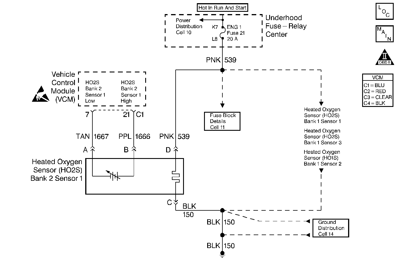
Circuit Description
Important: If this voltage is measured by using a 10 megaohm digital voltmeter, the voltage may read as low as 0.32 volt.
The Heated Oxygen Sensor (HO2S) varies the voltage within a range of about 1.0 volt (1000 mV) if the exhaust is rich to as low as 0.10 volt (10 mV) if the exhaust is lean.
The VCM supplies a reference voltage of approximately 0.45 volts (450 mV) to the Heated Oxygen sensor (HO2S) on the HO2S High signal circuit. When the Heated Oxygen sensor is cold, less than 200°C (392°F), the Heated Oxygen sensor signal voltage will read around 0.45 volt, and the VCM will keep the system in an Open Loop operation. When the Heated Oxygen sensor is warm, above 200°C (392°F), the Heated Oxygen sensor will swing from rich to lean rapidly, at least 1 swing every 2 seconds, if the VCM is in control of the air fuel mixture. This DTC sets if the Oxygen sensor is slow to respond to changes in the exhaust oxygen content.
When the HO2S temperature is below 360°C (600°F), the sensor will not produce any voltage and will behave like an open circuit. This will result in an Open Loop operation.
The HO2S heater provides for a faster sensor warm-up. This allows the sensor to become active in a shorter period of time and remain active during a long extended idle. This DTC is a type B DTC.
Conditions for Setting the DTC
| • | Lean to Rich switches to less than 50 |
| • | Rich to Lean switches to less than 50 |
| • | There are no TP sensor DTCs |
| • | There are no EVAP sensor DTCs |
| • | There are no IAT sensor DTCs |
| • | There are no MAP sensor DTCs |
| • | There are no ECT sensor DTCs |
| • | There are no MAF sensor DTCs |
| • | There is no intrusive test in progress |
| • | No device controls are active |
| • | The system voltage is at least 9.0 volts |
Response Test Enable
| • | Closed Loop |
| • | Closed loop low MAP is not active |
| • | DTCs P0151, P0152, P0154, and P0155 are not active |
| • | The ECT is greater than 57°C (134°F) |
| • | The engine run time is greater than 75 seconds |
| • | The MAF is at least 15 g/s and no more than 55 g/s |
| • | The engine speed is at least 1100 RPM and no more than 3000 RPM |
| • | The EVAP canister purge duty cycle is at least 0% |
| • | The above conditions are met for a time greater than 2 seconds. |
Action Taken When the DTC Sets
The VCM turns the MIL (Malfunction Indicator Lamp) ON after 2 consecutive test failures.
The VCM records the operating conditions at the time the diagnostic fails. The Freeze Frame and Failure Records store this information.
Conditions for Clearing the MIL or DTC
| • | The control module turns OFF the MIL after 3 consecutive drive trips when the test has run and passed. |
| • | A history DTC will clear if no fault conditions have been detected for 40 warm-up cycles. A warm-up cycle occurs when the coolant temperature has risen 22°C (40°F) from the startup coolant temperature and the engine coolant reaches a temperature that is more than 70°C (158°F) during the same ignition cycle. |
| • | Use a scan tool in order to clear the DTCs. |
Diagnostic Aids
Important: Never solder the HO2S wires. For proper wire and connector repairs, refer to Wiring Repairs.
Check for the following conditions:
| • | An improperly installed air intake duct |
| • | The air intake duct for collapsed ducting, restrictions, or a missing or plugged air filter |
| • | Throttle body and intake manifold vacuum leaks |
| • | A damaged or blocked throttle body inlet |
| • | Exhaust system for corrosion, leaks, or loose or missing hardware |
| • | The HO2S is installed securely and the pigtail harness is not contacting the exhaust manifold or wires |
| • | HO2S contamination |
| • | The vacuum hoses for splits, kinks, and proper connections |
| • | Excessive water, alcohol, or other contaminants in the fuel |
| • | VCM sensor grounds that are clean, tight, and properly positioned |
Test Description
The numbers below refer to the step numbers in the diagnostic table.
-
Diagnose other DTCs first because they may have set this DTC.
-
With the engine running warm, coolant at least 85°C (185°F) and at fast idle, the HO2S voltage should rapidly swing above 0.60 volts and below 0.30 volts.
-
This step checks to see if the Oxygen sensor voltage is swinging between rich and lean very slowly or not at all.
-
This step checks for causes of the HO2S failure. If the sensor is replaced without finding the cause of the contamination, the replacement sensor may become contaminated.
Step | Action | Value(s) | Yes | No | ||||||||||
|---|---|---|---|---|---|---|---|---|---|---|---|---|---|---|
1 |
Important: Before clearing the DTCs, use the scan tool in order to record the Freeze Frame and the Failure Records for reference. This data will be lost when the Clear DTC Information function is used. Was the Powertrain On-Board Diagnostic (OBD) System Check performed? | -- | ||||||||||||
Connect the scan tool. Are any other DTCs stored? | -- | Go to the applicable DTC table | ||||||||||||
After 2 minutes, does the HO2S voltage rapidly fluctuate above and below the specified value? | 1200-2000 RPM 0.30-0.60 V | |||||||||||||
4 | Operate the engine at a steady speed within the specified range. Does the scan tool display indicate a Closed Loop? | 1200-2000 RPM | Go to Diagnostic Aids | |||||||||||
Does the HO2S voltage stay within the specified value longer than it swings outside this value? | 1200-2000 RPM 0.30-0.60 V | |||||||||||||
6 | Check the VCM connector terminal contact at the HO2S Signal and Low circuits. Was a problem found? | -- | ||||||||||||
7 | Check for a poor connection at the HO2S connector. Was a problem found? | -- | ||||||||||||
Check the following as possible causes of HO2S contamination:
Was a problem found and repaired? | -- | |||||||||||||
9 | Replace the HO2S. Refer to Heated Oxygen Sensor (HO2S) Replacement . Is the action complete? | -- | -- | |||||||||||
10 | Repair as necessary. Is the action complete? | -- | -- | |||||||||||
11 |
Does the scan tool indicate that this diagnostic ran and passed? | -- | ||||||||||||
12 | Use the scan tool in order to display the Capture Info and the Review Capture Info functions. Are there any DTCs displayed that have not been diagnosed? | -- | Go to the applicable DTC table | System OK |
