Circuit Description
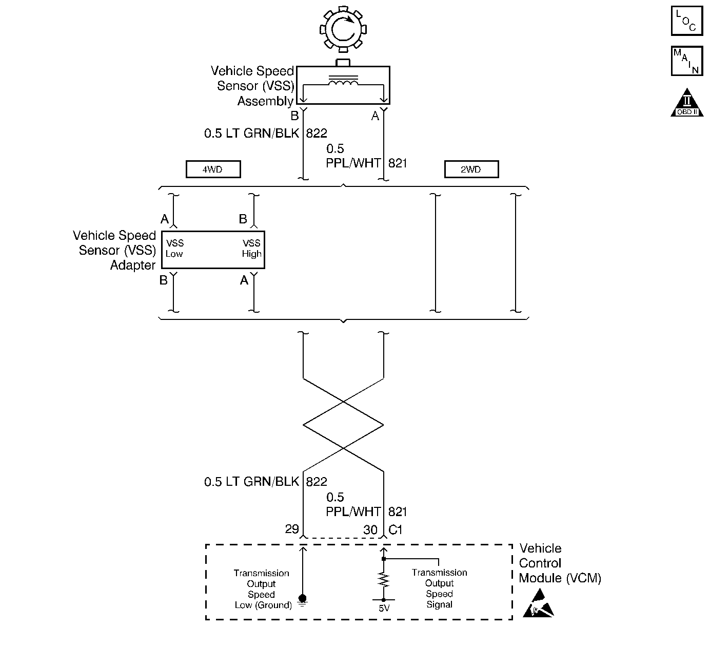
The Vehicle Speed Sensor Assembly (VSS Assy.) provides vehicle speed information to the VCM. The VSS Assy. is a Permanent Magnet (PM) generator. The PM generator produces a pulsing AC voltage. The AC voltage level and the number of pulses increase with the speed of the vehicle. The VCM then converts the pulsing voltage to vehicle speed. The VCM uses this information for calculations. A scan tool can display the vehicle speed.
When the VCM detects a low vehicle speed when there is a high engine speed in a drive gear range, then DTC P0502 sets. DTC P0502 is a type A DTC.
Conditions for Setting the DTC
| • | No MAP DTCs P0107 or P0108 |
| • | No TP DTCs P0122 or P0123 |
| • | No TFP Val. Position Sw. DTC P1810 |
| • | The transmission is not in Park or Neutral. |
| • | The TP angle is greater than 20%. |
| • | The engine vacuum is 0-106 kPa. |
| • | The engine speed is greater than 3000 RPM. |
| • | The engine torque is 40 -400 ft lb. |
| • | The transmission output speed is less than 150 RPM. |
| • | All conditions met for 2.5 seconds |
Action Taken When the DTC Sets
| • | The VCM commands second gear only. |
| • | The VCM commands maximum line pressure. |
| • | The VCM freezes shift adapts from being updated. |
| • | The VCM inhibits TCC engagement. |
| • | The VCM illuminates the Malfunction Indicator Lamp (MIL). |
Conditions for Clearing the MIL/DTC
| • | The VCM turns OFF the MIL after three consecutive ignition cycles without a failure reported. |
| • | A scan tool can clear the DTC from the VCM history. The VCM clears the DTC from the VCM history if the vehicle completes 40 warm-up cycles without a failure reported. |
| • | The VCM cancels the DTC default actions when the fault no longer exists and the ignition is OFF long enough in order to power down the VCM. |
Diagnostic Aids
| • | Inspect the wiring for poor electrical connections at the VCM. Look for the following conditions: |
| - | A bent terminal |
| - | A backed out terminal |
| - | A damaged terminal |
| - | Poor terminal tension |
| - | A chafed wire |
| - | A broken wire inside the insulation |
| • | When diagnosing for an intermittent short or open condition, massage the wiring harness while watching the test equipment for a change. |
Test Description
The numbers below refer to the step numbers on the diagnostic chart.
-
This step tests the VSS Assy. circuit.
-
This step tests the integrity of the VSS Assy.
-
This step tests the 5-volt and ground circuit of the VCM.
Step | Action | Value(s) | Yes | No |
|---|---|---|---|---|
1 | Was the Powertrain On-Board Diagnostic (OBD) System Check performed? | -- | Go to Powertrain On Board Diagnostic (OBD) System Check (4.3L) Powertrain On Board Diagnostic (OBD) System Check (5.0L and 5.7L) | |
2 |
Important: Before clearing the DTCs, use the scan tool in order to record the Freeze Frame and Failure Records for reference. The Clear Info function will erase the data. With the drive wheels rotating, does the Trans Output Speed increase with the drive wheel speed? | -- | Go to Diagnostic Aids | |
3 | Does the speedometer work? | -- | ||
4 | Check for the most current calibration. Check for an incorrect calibration. Refer to the Service Bulletin. Is the calibration current? | -- | ||
5 | Reprogram the VCM. Refer to Section 6: EEPROM Programming (4.3L) EEPROM Programming (5.0L and 5.7L) Has the VCM been reprogrammed? | -- | -- | |
Is the resistance within the specified range? | 1480-2700ohms | |||
Is the voltage greater than the specified value? | 0.5 volts | |||
8 | Inspect circuits 821 and 822 for a poor connection or an open circuit. Did you find a problem? | -- | ||
Is the voltage within the specified range? | 4.0-5.1 volts | |||
10 |
Did you find a problem? | -- | ||
11 | Replace the VSS Assy. Refer to Vehicle Speed Sensor Assembly Replacement, in On-Vehicle Service. Is the replacement complete? | -- | -- | |
12 | Was the voltage measured in Step 9 less than the voltage in the value column? | 4.0 volts | ||
13 | Was the voltage measured in Step 9 greater than the voltage in the value column? | 5.1 volts | -- | |
14 | Repair the short to B+ in circuit 821. Refer to Electrical Diagnosis, Section 8. Is the repair complete? | -- | -- | |
15 | Replace the VCM. Refer to Section 6: VCM Replacement/Programming (4.3L) VCM Replacement/Programming (5.0L and 5.7L) Is the replacement complete? | -- | -- | |
16 | In order to verify your repair, perform the following procedure:
Has the test run and passed? | -- | System OK |
