OIL PUMP ROTOR AND SLIDE SERVICE PROCEDURE 2004R/700R4

VEHICLES AFFECTED: Vehicles Equipped With THM 200-4R and 700-R4 Transmissions
Beginning mid November, 1983, service parts became available to service the oil pump rotor and slide of the pump body on all THM 200-4R and 700-R4 transmissions. This service procedure on all THM 200-4R and 700-R4 transmissions must be followed to assure proper end clearance on the oil pump rotor and slide.
SERVICE PROCEDURE:
NOTICE; DO NOT attempt to service the oil pump rotor if either the pump body pocket or pump body cover surfaces are scored. Servicing of the oil pump rotor and slide should be performed ONLY if the selective pump rotor, or the slide show wear.
1. Disassembly of the oil pump
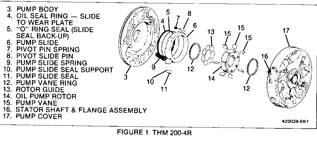
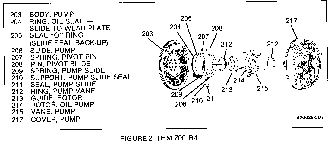
A. Disassemble the oil pump body assembly following procedures outlined in the sevice manual. Refer to figure 1 for the THM 200-4R and figure 2 for the THM 700-R4 transmission oil pump body assembly.
2. Selecting the pump rotor and slide.
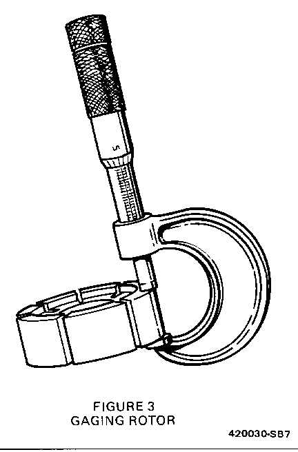
A. Use a micrometer to measure the original pump rotor and slide thickness accurately (Figure 3). To obtain the most accurate reading, measure on flat undamaged surfaces. The oil pump rotor and slides for the THM 200-4R and the THM 700-R4 transmissions are the same.
B. Using the original part measurement, order replacement parts according to the following selective charts.
CHART NUMBER 1
All THM 200-4R and 700-R4 Selective Pump Rotor
PART NUMBER THICKNESS IN MM THICKNESS IN INCHES ------------ ---------------- -------------------- 8634091 17.948 - 17.961 0.7066 - 0.7071 8634092 17.961 - 17.974 0.7071 - 0.7076 8634093 17.974 - 17.987 0.7076 - 0.7081 8634094 17.987 - 18.000 0.7081 - 0.7086 8634095 18.000 - 18.013 0.7086 - 0.7091
CHART NUMBER 2
All THM 200-4R and 700-4R Selective Pump Slide
PART NUMBER THICKNESS IN MM THICKNESS IN INCHES ------------ --------------- -------------------- 8634081 17.948 - 17.961 0.7066 - 0.7071 8634082 17.961 - 17.974 0.7071 - 0.7076 8634083 17.974 - 17.987 0.7076 - 0.7081 863408.1 17.987 - 18.000 0.7081 - 0.7086 8634085 18.000 - 18.013 0.7086 - 0.7091
NOTE: The replacement part will provide the same clearance that the oil pump assembly was originally built with. The proper end clearance specification is 0.020 to 0.050 mm or (.0008 in) to (.002 in) for the 200-4R and the 700-R4.
C. Hone both sides of the replacement rotor and slide to remove any burrs, and measure the replacement parts with a micrometer to assure proper selection.
NOTE: Incorrect rotor selection could result in a damaged oil pump assembly, and/or low pressure. Incorrect slide selection could result in incorrect line pressure.
3. Assembly:
A. Reassemble the oil pump assembly following procedures outlined in the service manual.
B. After assembling the oil pump onto the transmission, install the converter and check for proper rotor and slide clearance by turning the converter. The converter should turn freely. If the converter does not turn freely, recheck the pump rotor and slide selection.
C. Install the transmission into the vehicle.
D. Before road testing the vehicle, install an oil pressure gauge into the transmission and check oil pressure. Refer to the service manual for oil pressure specifications.
General Motors bulletins are intended for use by professional technicians, not a "do-it-yourselfer". They are written to inform those technicians of conditions that may occur on some vehicles, or to provide information that could assist in the proper service of a vehicle. Properly trained technicians have the equipment, tools, safety instructions and know-how to do a job properly and safely. If a condition is described, do not assume that the bulletin applies to your vehicle, or that your vehicle will have that condition. See a General Motors dealer servicing your brand of General Motors vehicle for information on whether your vehicle may benefit from the information.
