GM Service Manual Online
For 1990-2009 cars only
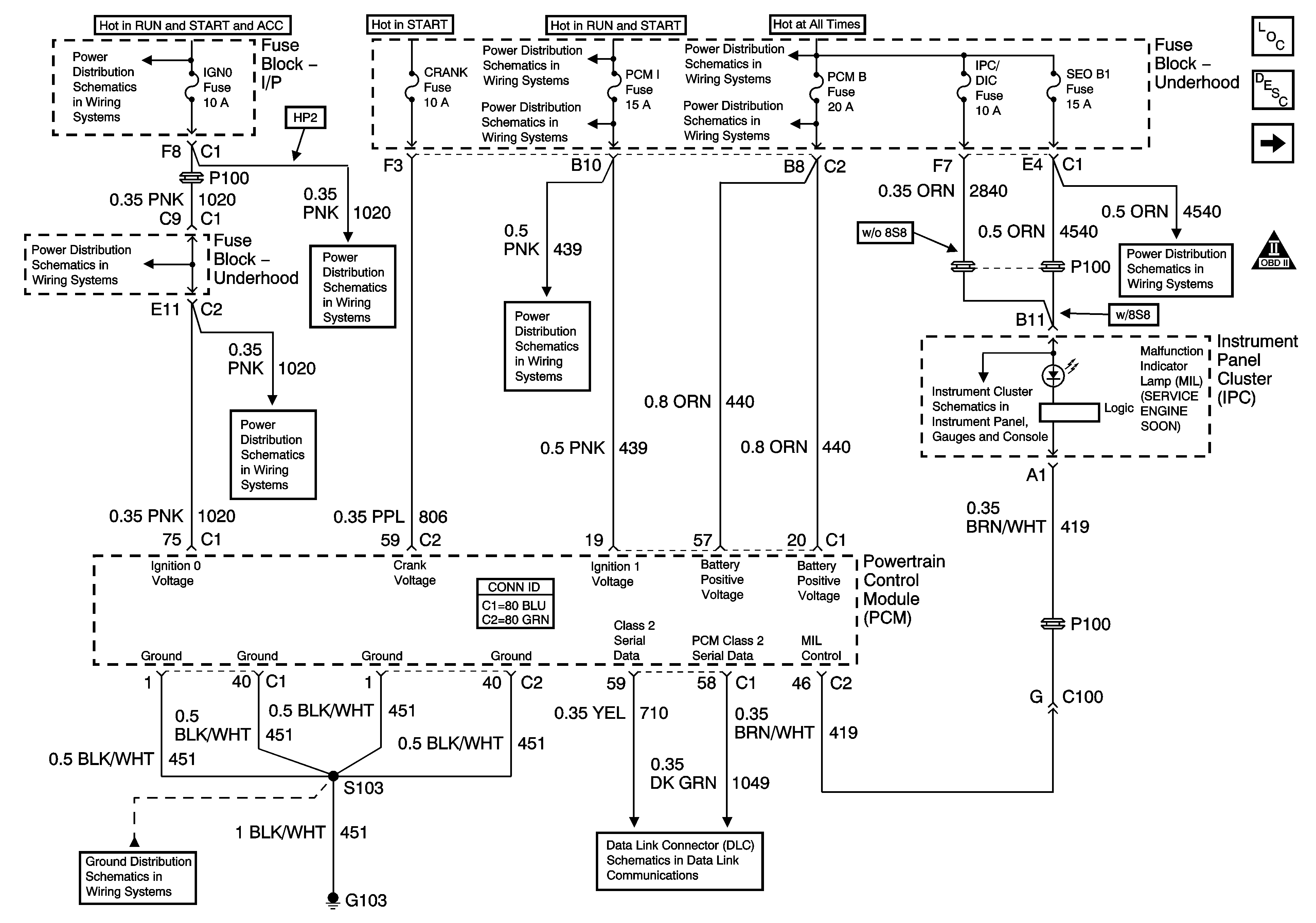
Figure 1:

Module Power, Ground, Serial Data, and MIL

Object Number: 1226777  Size: FS
Master Electrical Component List
Powertrain Control Module Description
Engine Data Sensors - Pressure, Temperature and VSS
OBD II Symbol Description Notice
Ignition Switch - START, RUN, and ACC/RUN/START Bus Bars
B+ Bus Bar - 2 of 2
SBA, ETC/ECM, PCM 1, BTSI, and TRL B/U Fuses
B+ Bus Bar - 1 of 2
PCM B, ECMRPV, EDU Fuses, F/PMP and EDU/IGN 1 Relays - Diesel Only
IGN 0, TBC IGN 0,TBC ACCY, SEO ACCY, RR WPR, and WS WPR Fuses
SBA, ETC/ECM, PCM 1, BTSI, and TRL B/U Fuses
Indicators
RTD, IPC/DIC, SEO B1, SUNROOF, EAP, and RR WPR Fuses
G103 - Gas
SP205 - 2 of 2
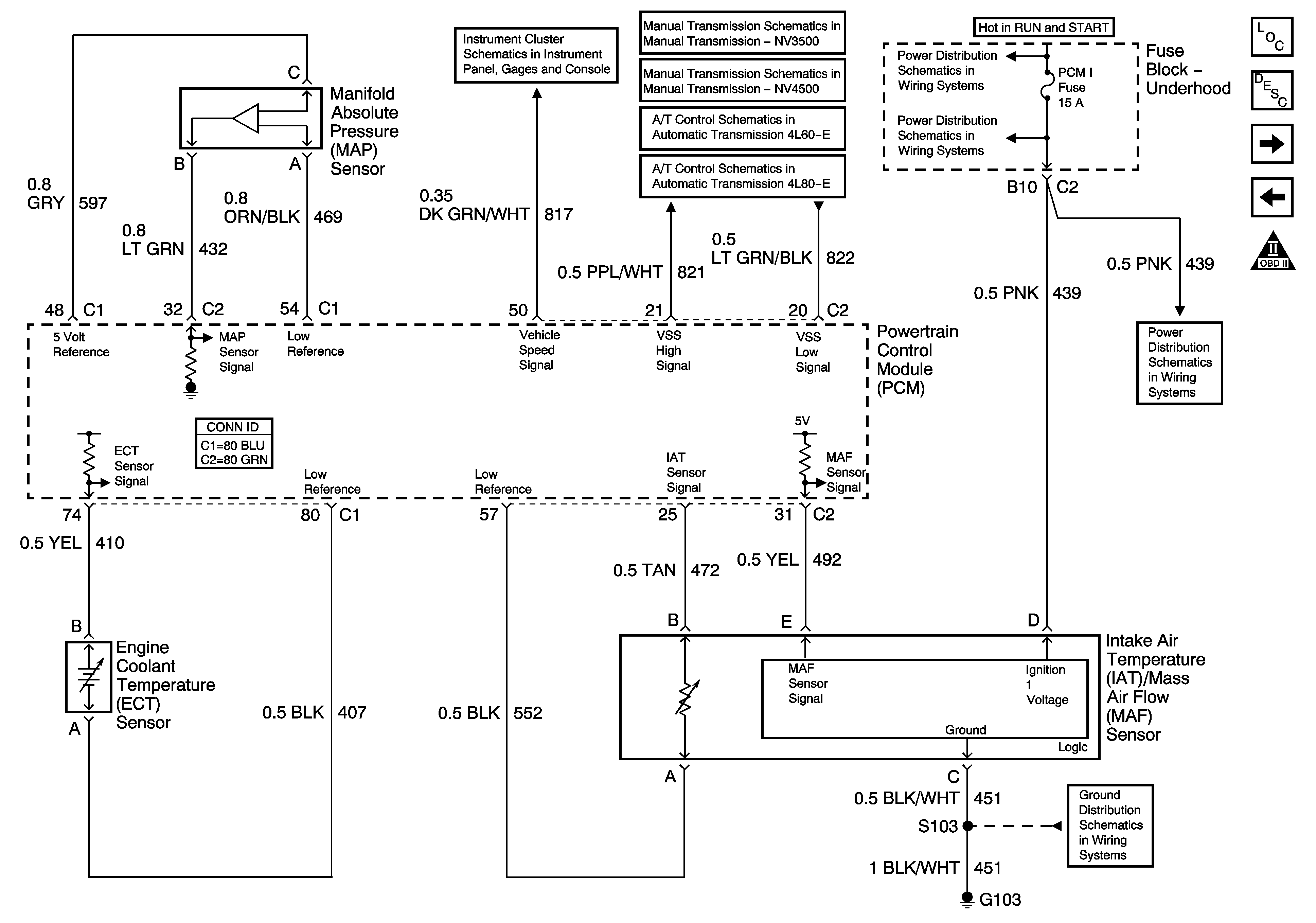
Figure 2:

Engine Data Sensors - Pressure, Temperature, and VSS

Object Number: 1226781  Size: FS
Master Electrical Component List
Powertrain Control Module Description
Engine Data Sensors - HO2S
Module Power, Ground, Serial Data and MIL
OBD II Symbol Description Notice
Vehicle Speed and Speedometer
Manual Transmission Schematics
Vehicle Speed and 4WD Signal
Vehicle Speed Signal and 4WD Low Signal
B+ Bus Bar - 2 of 2
SBA, ETC/ECM, PCM 1, BTSI, and TRL B/U Fuses
G103 - Gas
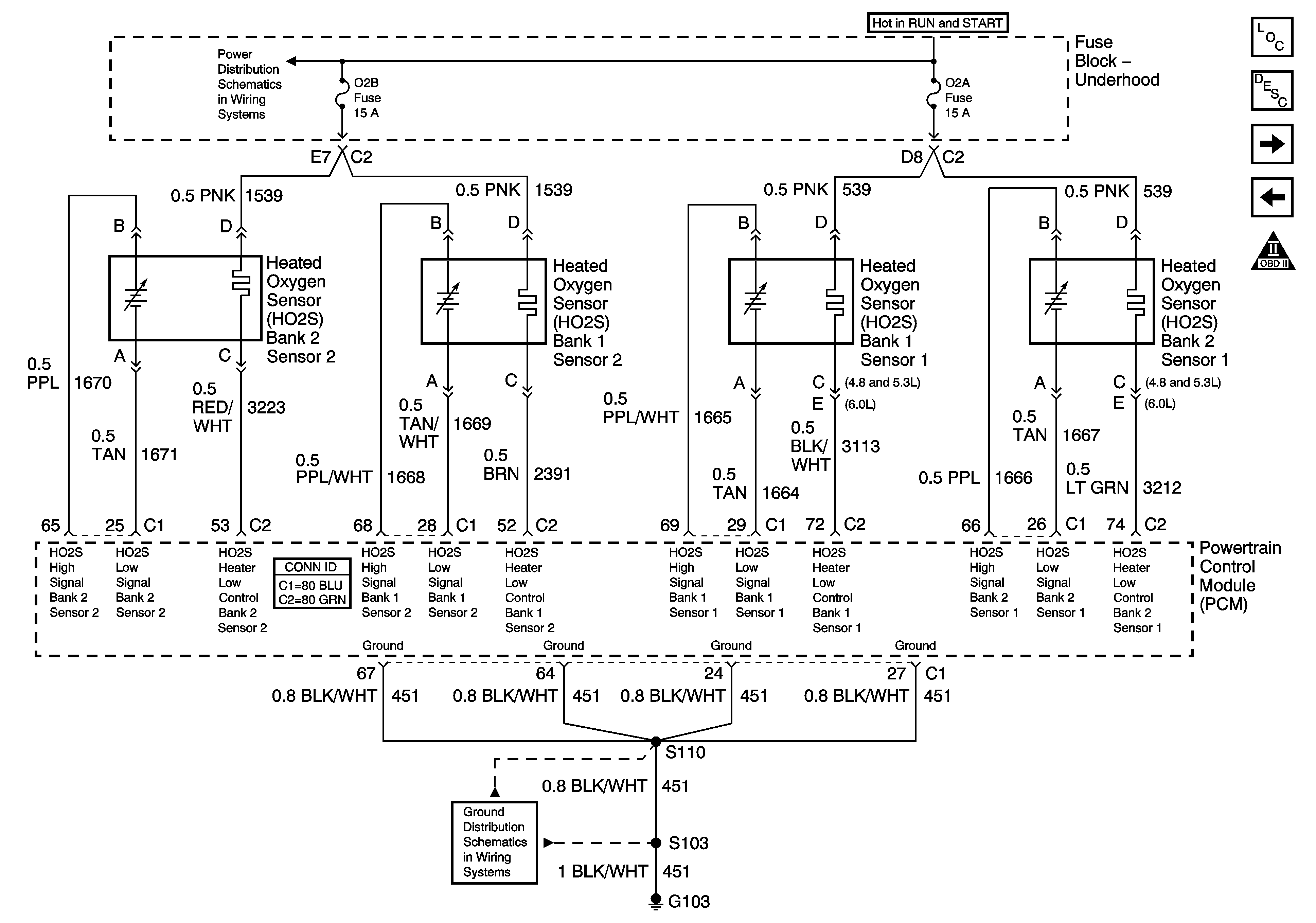
Figure 3:

Engine Data Sensors - HO2S


Object Number: 1226784  Size: FS
Master Electrical Component List
Powertrain Control Module Description
Engine Data Sensors - HO2S - HP2 - 1 of 2
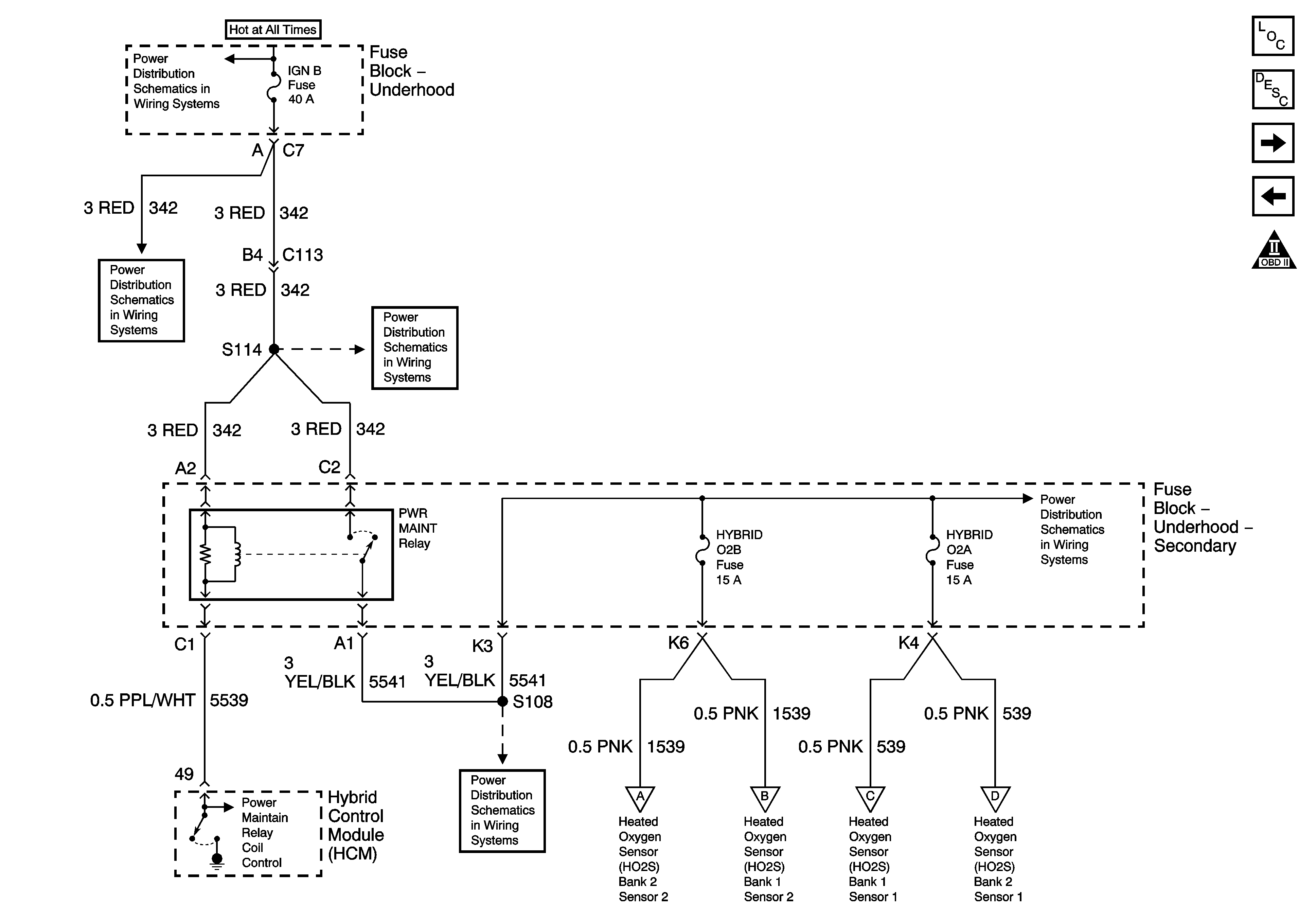
Engine Data Sensors - Pressure, Temperature and VSS
OBD II Symbol Description Notice
Ignition Switch - ACC/RUN and RUN/START Bus Bars
G103 - Gas
Figure 4:

Engine Data Sensors - HO2S - HP2 - 1 of 2


Object Number: 1388095  Size: FS
Master Electrical Component List
Powertrain Control Module Description
Engine Data Sensors - HO2S - HP2 - 2 of 2
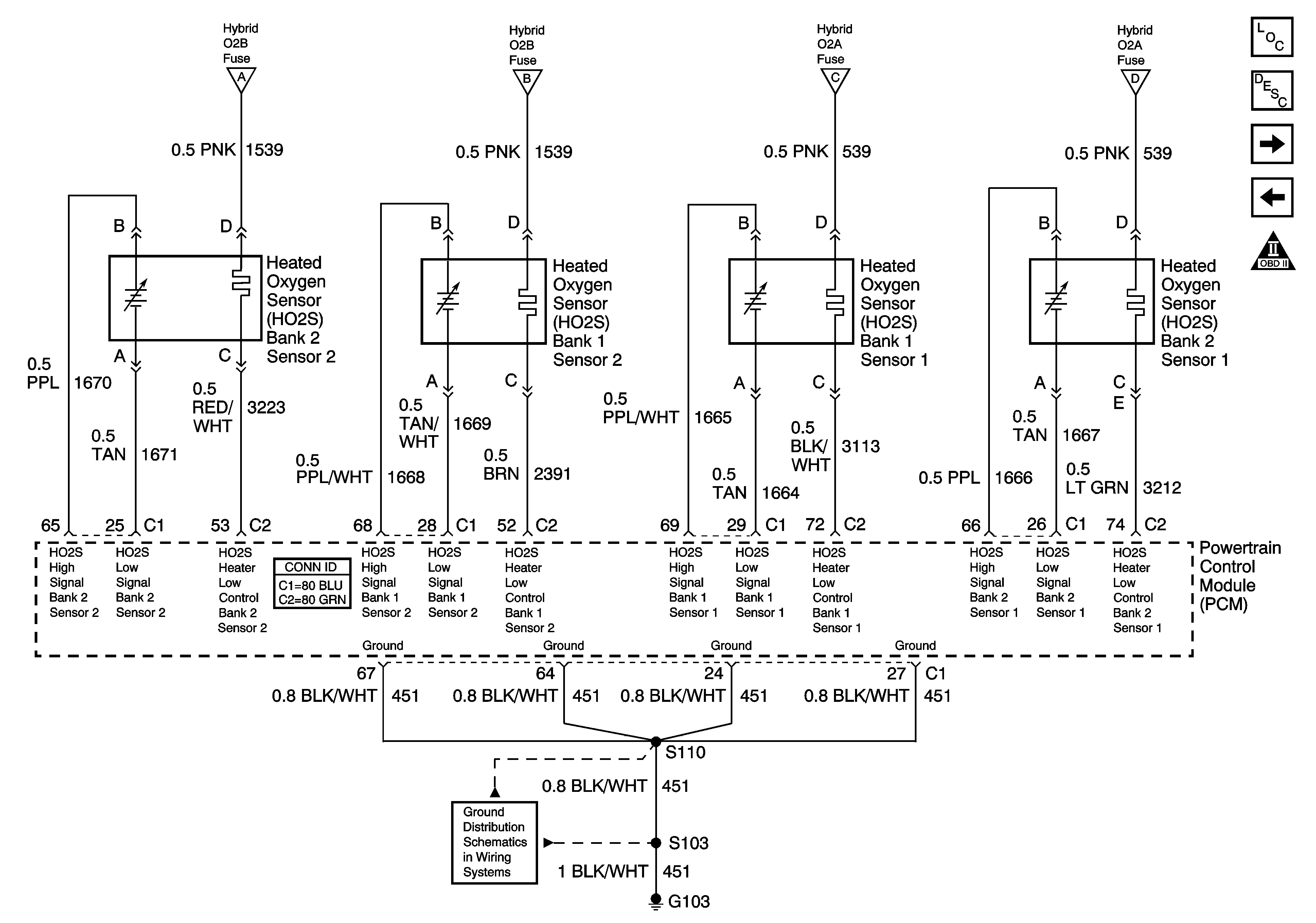
Engine Data Sensors - HO2S
Engine Controls Schematic Icons
B+ Bus Bar - 1 of 2
Ignition Switch - ACC/RUN and RUN/START Bus Bars
Continuous Mode Bus Bar (HP2)
Engine Data Sensors - HO2S - HP2 - 2 of 2
Continuous Mode Bus Bar (HP2)
Figure 5:

Engine Data Sensors - HO2S - HP2 - 2 of 2


Object Number: 1388098  Size: FS
Master Electrical Component List
Powertrain Control Module Description
Engine Data Sensors - Electronic Throttle Controls - 1 of 2
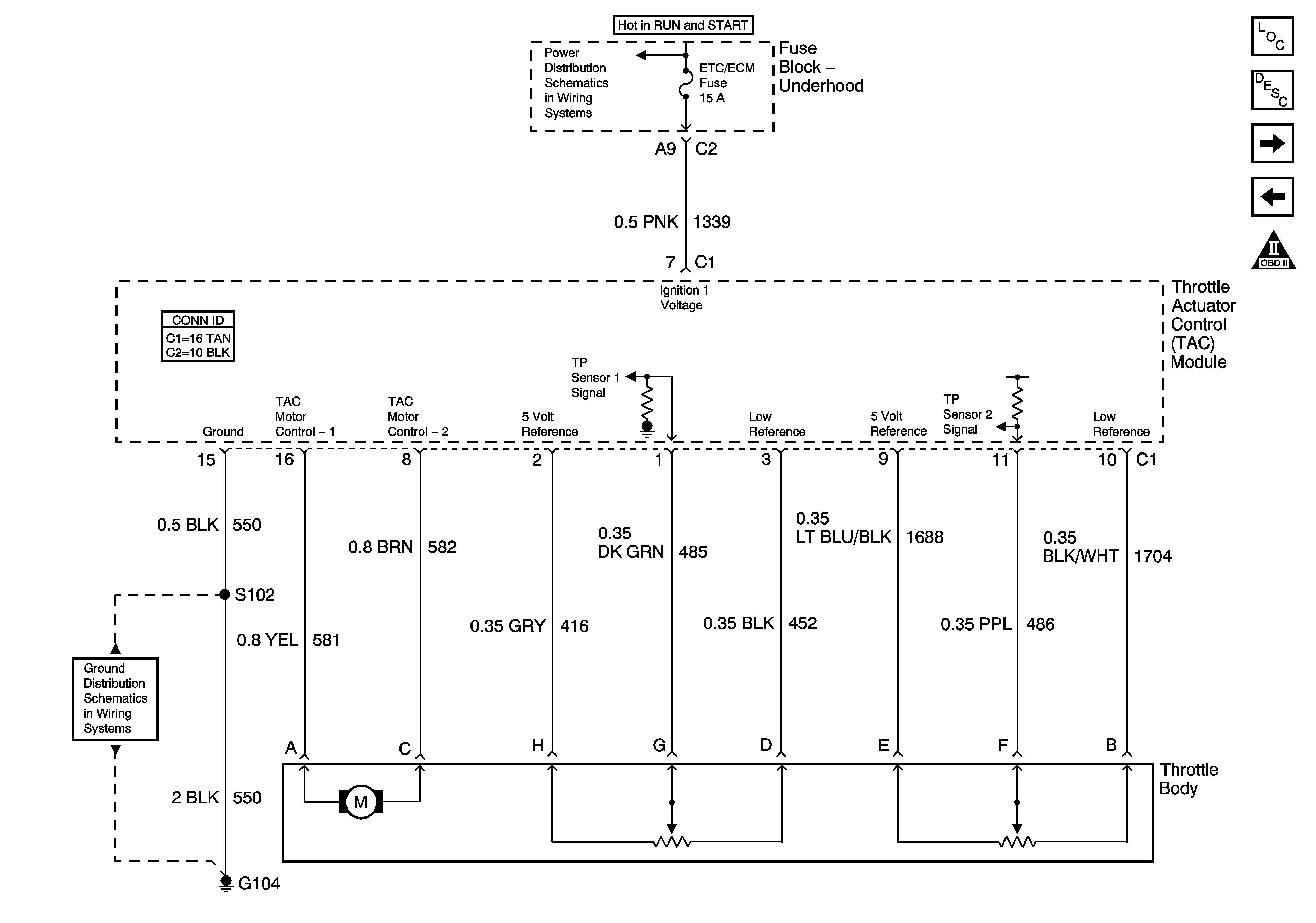
Engine Data Sensors - HO2S - HP2 - 1 of 2
Engine Controls Schematic Icons
Engine Data Sensors - HO2S - HP2 - 1 of 2
G103 - Gas
Figure 6:

Engine Data Sensors - Electronic Throttle Controls - 1 of 2


Object Number: 1226793  Size: FS
Master Electrical Component List
Powertrain Control Module Description
Engine Data Sensors - Electronic Throttle Controls - 2 of 2
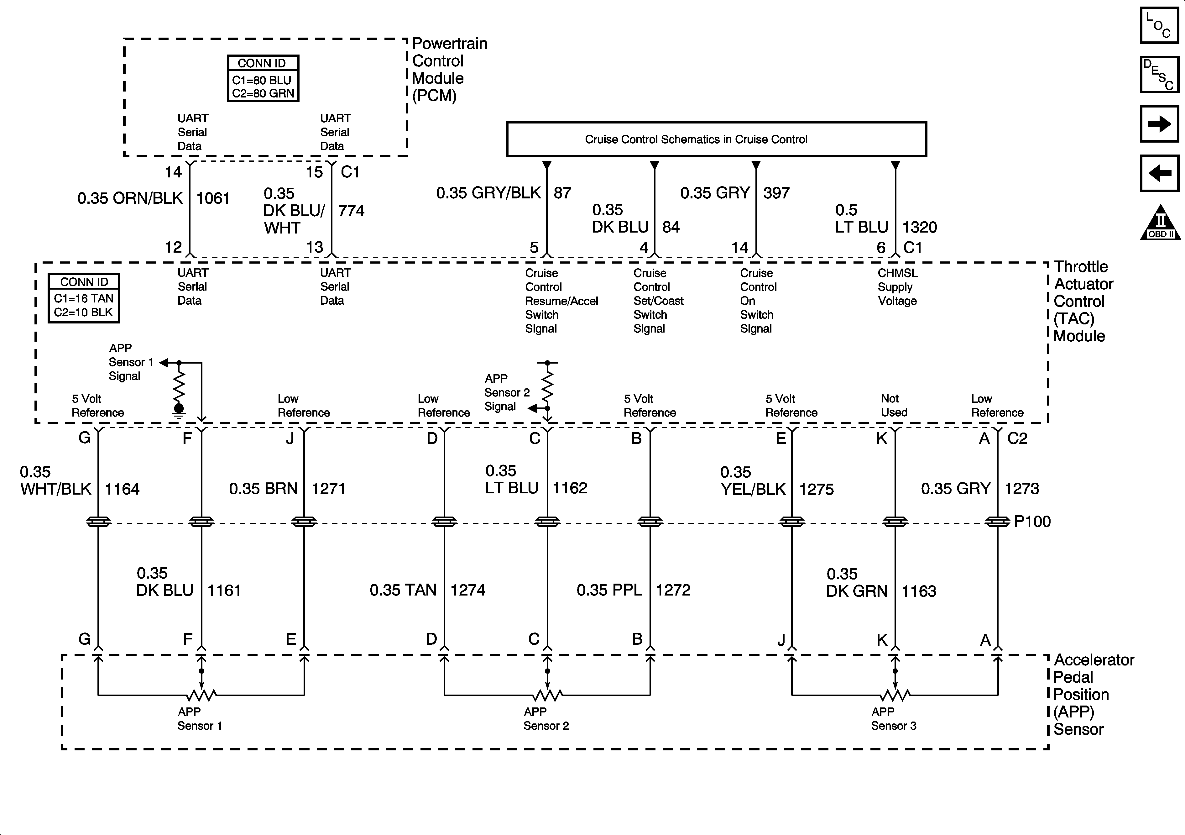
Engine Data Sensors - HO2S - HP2 - 2 of 2
OBD II Symbol Description Notice
B+ Bus Bar - 2 of 2
G104, G106, and G107
Figure 7:

Engine Data Sensors - Electronic Throttle Controls - 2 of 2


Object Number: 1226798  Size: FS
Master Electrical Component List
Powertrain Control Module Description
Ignition Controls - Ignition System Coils 1, 3, 5 and 7
Engine Data Sensors - Electronic Throttle Controls - 1 of 2
OBD II Symbol Description Notice
4.8, 5.3, 6.0, and 8.1L - 1 of 2
Figure 8:

Ignition Controls - Ignition System Coils 1, 3, 5, and 7
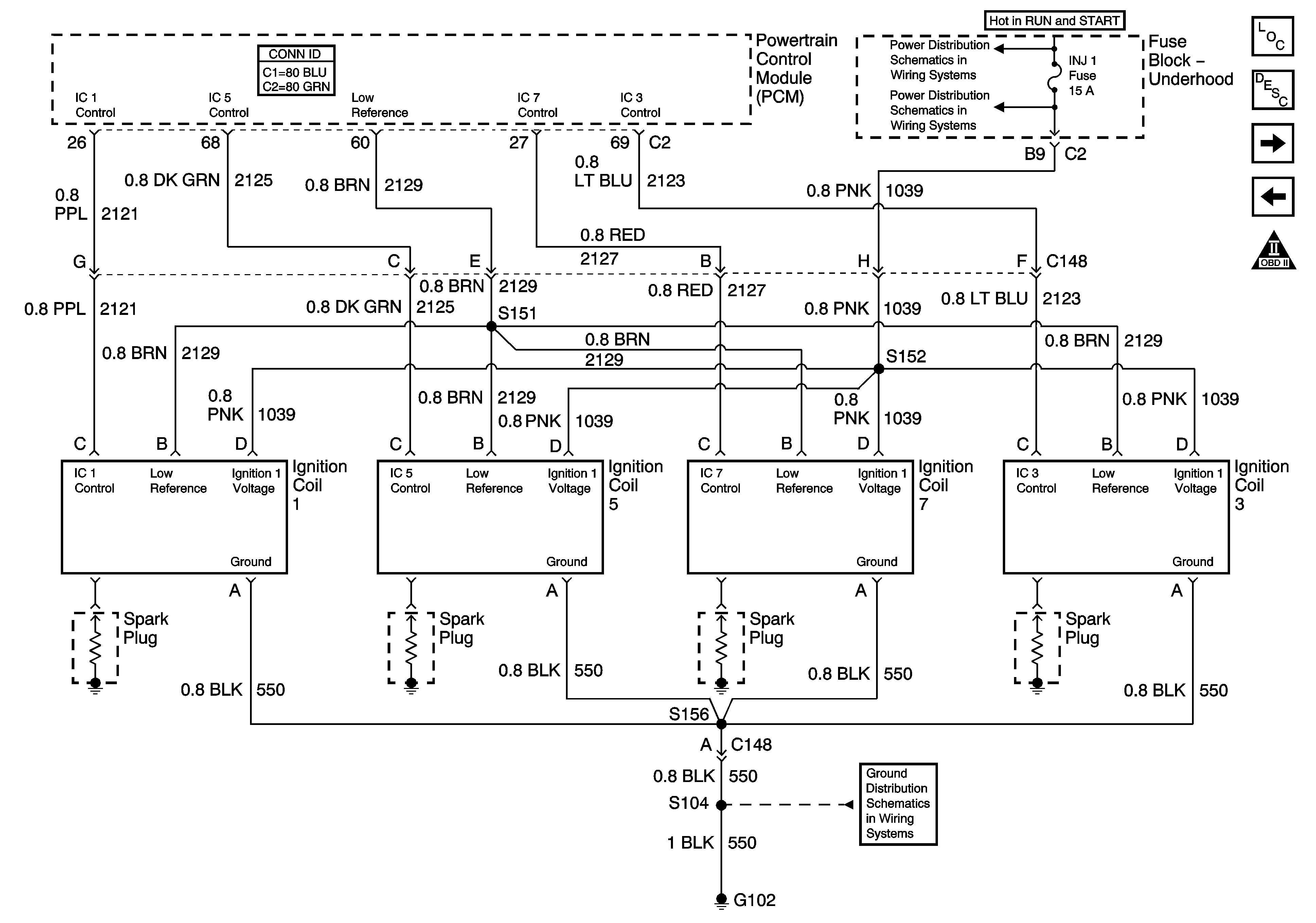

Object Number: 1226803  Size: FS
Master Electrical Component List
Powertrain Control Module Description
Ignition Controls - Ignition System Coils 2, 4, 6 and 8
Engine Data Sensors - Electronic Throttle Controls - 2 of 2
OBD II Symbol Description Notice
B+ Bus Bar - 2 of 2
INJ 1and INJ 2 Fuses - Gas Except 8.1L
G104, G106, and G107
Figure 9:

Ignition Controls - Ignition System Coils 2, 4, 6, and 8
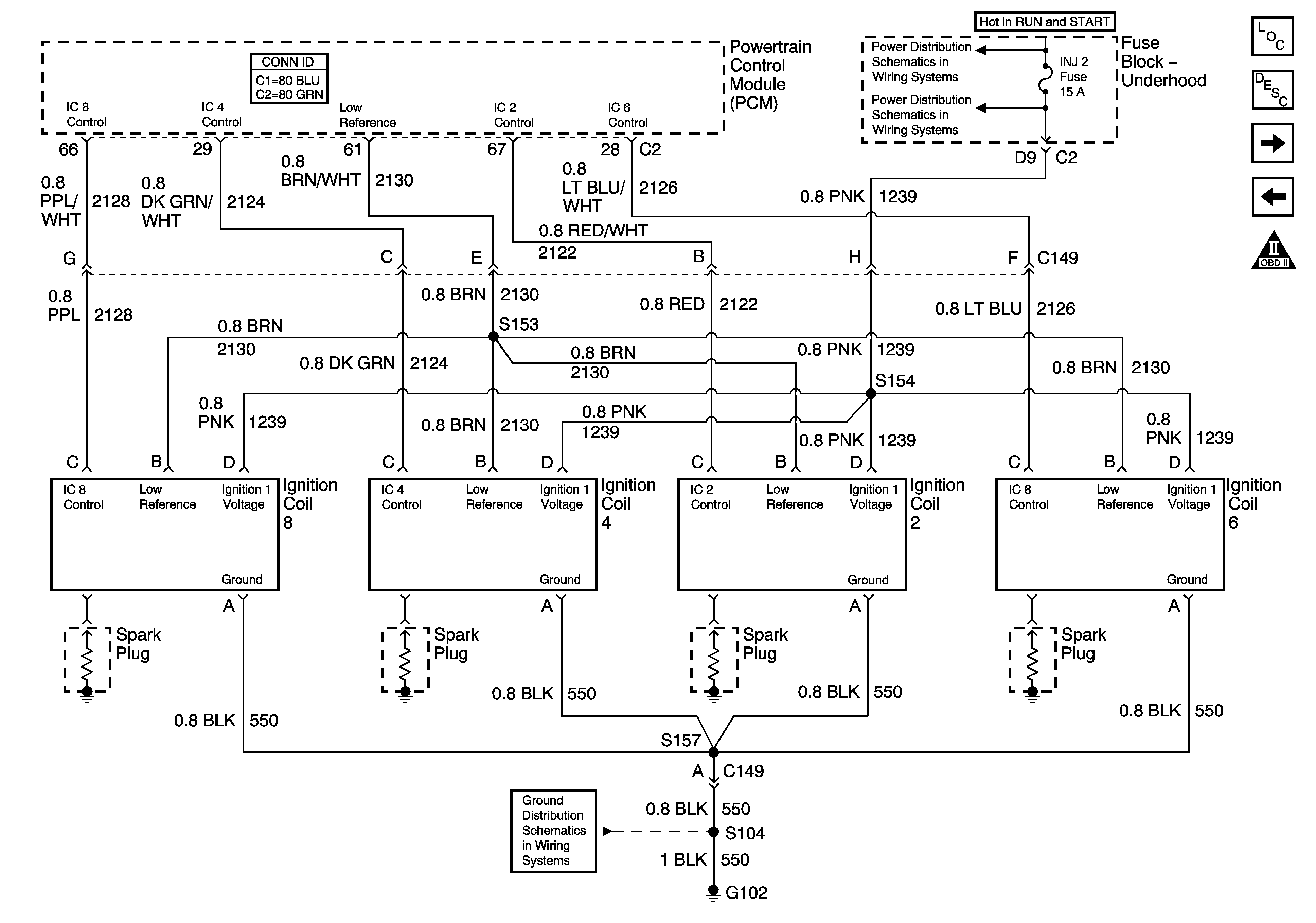

Object Number: 1226805  Size: FS
Master Electrical Component List
Powertrain Control Module Description
Ignition Controls - Sensors
Ignition Controls - Ignition System Coils 1, 3, 5 and 7
OBD II Symbol Description Notice
B+ Bus Bar - 2 of 2
INJ 1and INJ 2 Fuses - Gas Except 8.1L
G104, G106, and G107
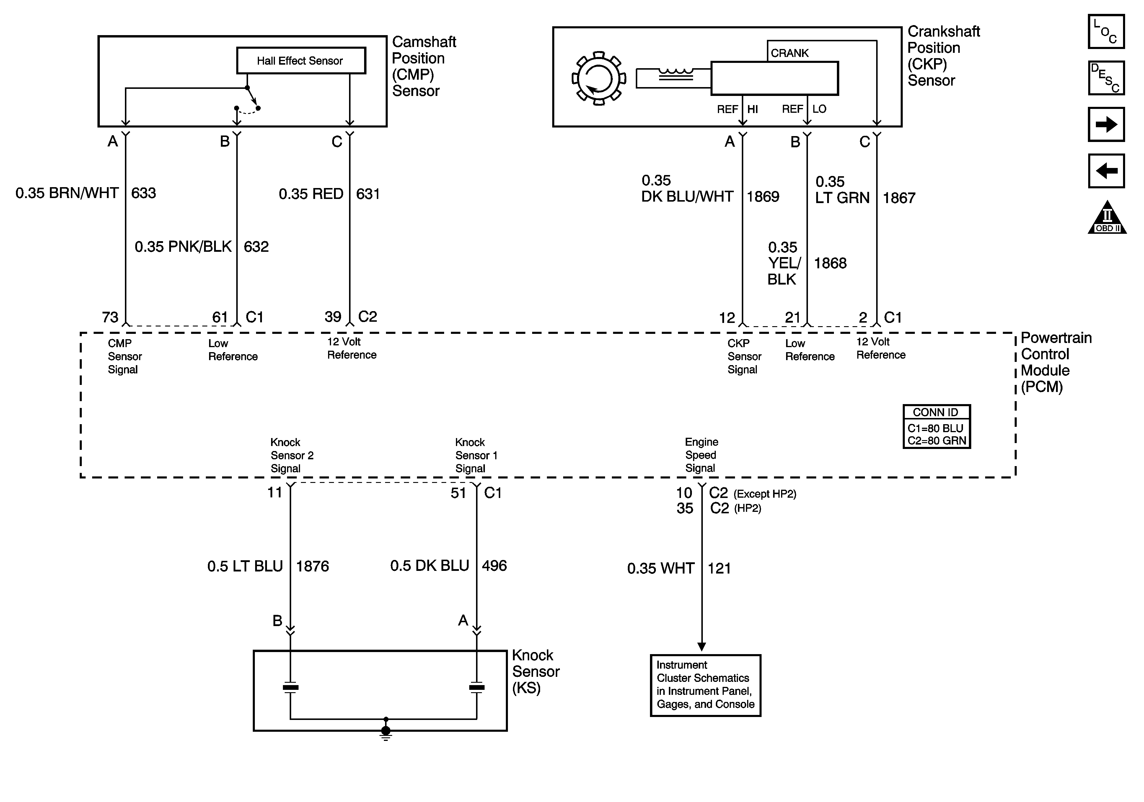
Figure 10:

Ignition Controls - Sensors


Object Number: 1226806  Size: FS
Master Electrical Component List
Powertrain Control Module Description
Fuel Controls - Fuel Pump Controls
Ignition Controls - Ignition System Coils 2, 4, 6 and 8
OBD II Symbol Description Notice
Gages
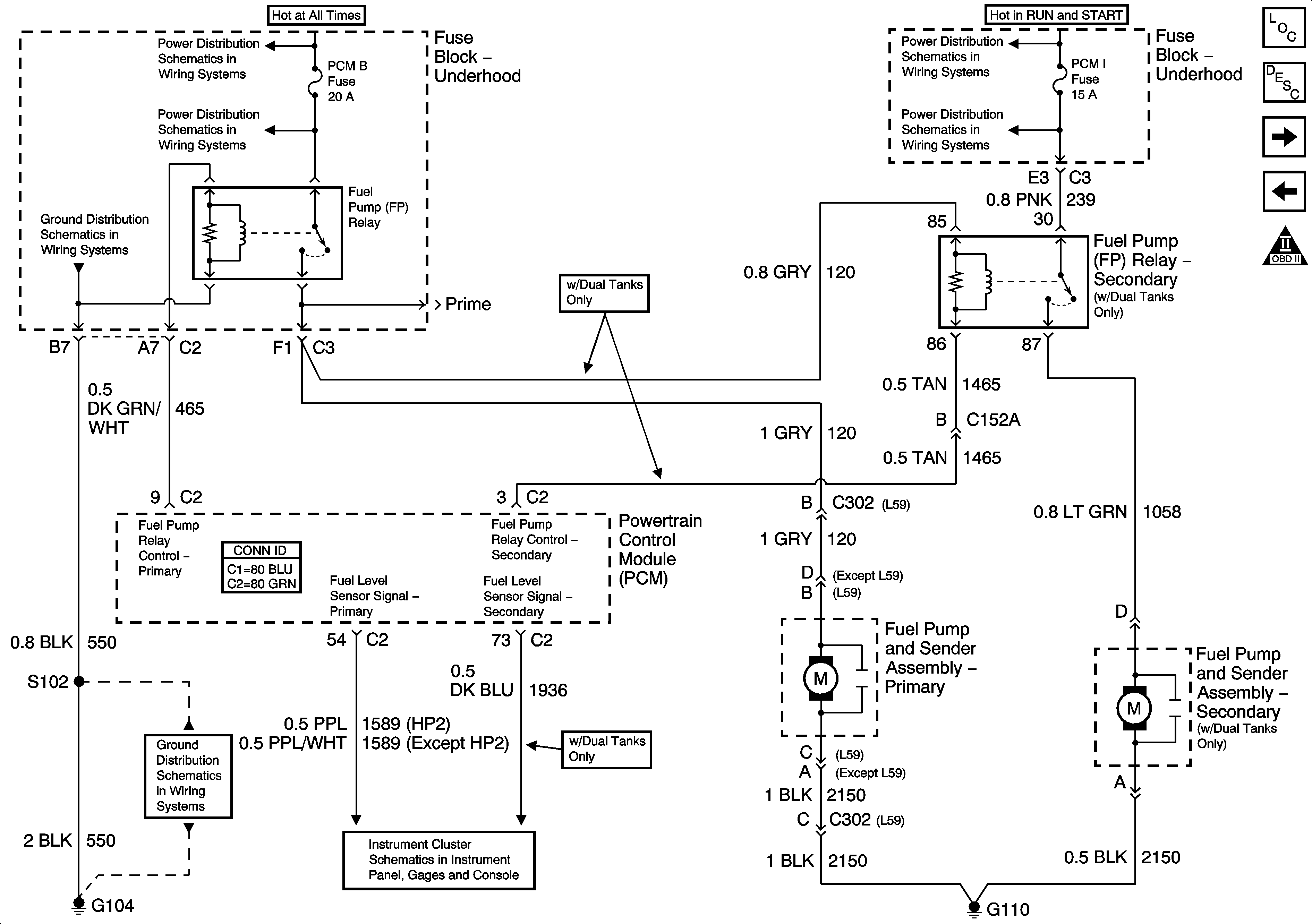
Figure 11:

Fuel Controls - Fuel Pump Controls


Object Number: 1226807  Size: FS
Master Electrical Component List
Powertrain Control Module Description
Fuel Controls - Fuel Injectors
Ignition Controls - Sensors
OBD II Symbol Description Notice
B+ Bus Bar - 2 of 2
LH HID, RH HID, PCM B, CRANK, HORN, and SIR Fuses
B+ Bus Bar - 2 of 2
SBA, ETC/ECM, PCM 1, BTSI, and TRL B/U Fuses
G104, G106, and G107
Fuel Gage
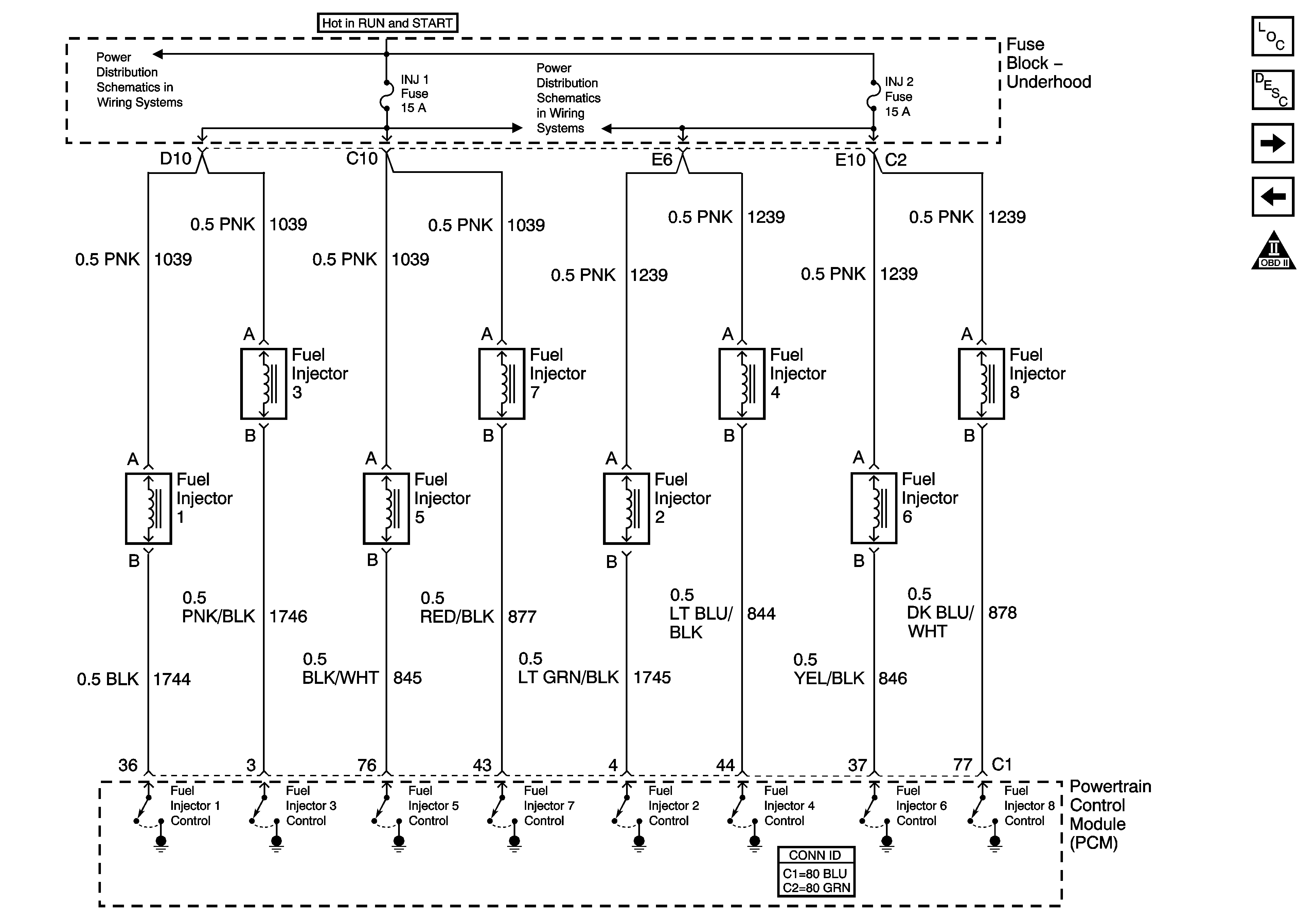
Figure 12:

Fuel Controls - Fuel Injectors


Object Number: 1226808  Size: FS
Master Electrical Component List
Powertrain Control Module Description
Fuel Controls - EVAP Controls and Fuel Tank Pressure
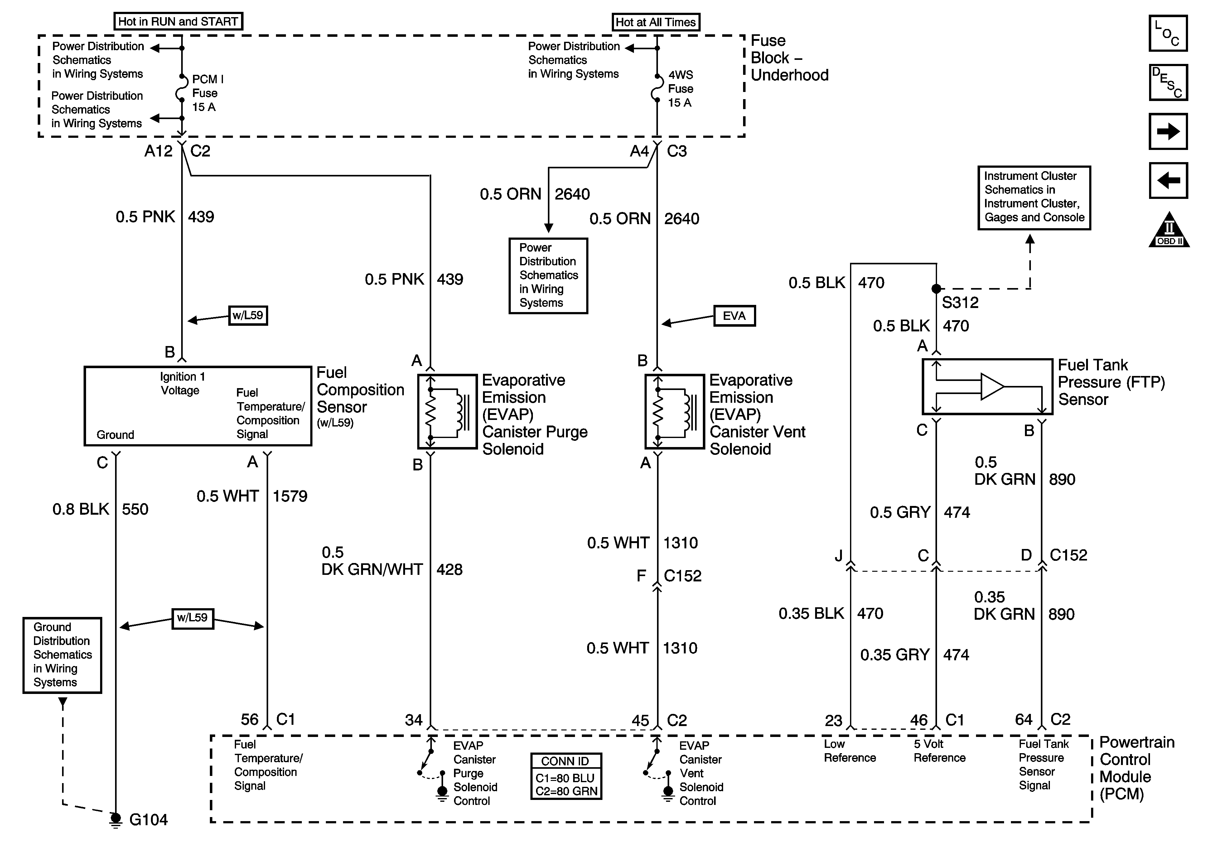
Fuel Controls - Fuel Pump Controls
OBD II Symbol Description Notice
B+ Bus Bar - 2 of 2
INJ 1and INJ 2 Fuses - Gas Except 8.1L
Figure 13:

Fuel Controls - EVAP Controls and Fuel Tank Pressure


Object Number: 1226812  Size: FS
Master Electrical Component List
Powertrain Control Module Description
Controlled/Monitored Subsystem Schematics - 1 of 2
Fuel Controls - Fuel Injectors
OBD II Symbol Description Notice
B+ Bus Bar - 2 of 2
SBA, ETC/ECM, PCM 1, BTSI, and TRL B/U Fuses
B+ Bus Bar - 1 of 2
4WS, RADIO, and RADIO AMP Fuses
Fuel Gage
G104, G106, and G107
Figure 14:

Controlled/Monitored Subsystem References - 1 of 2
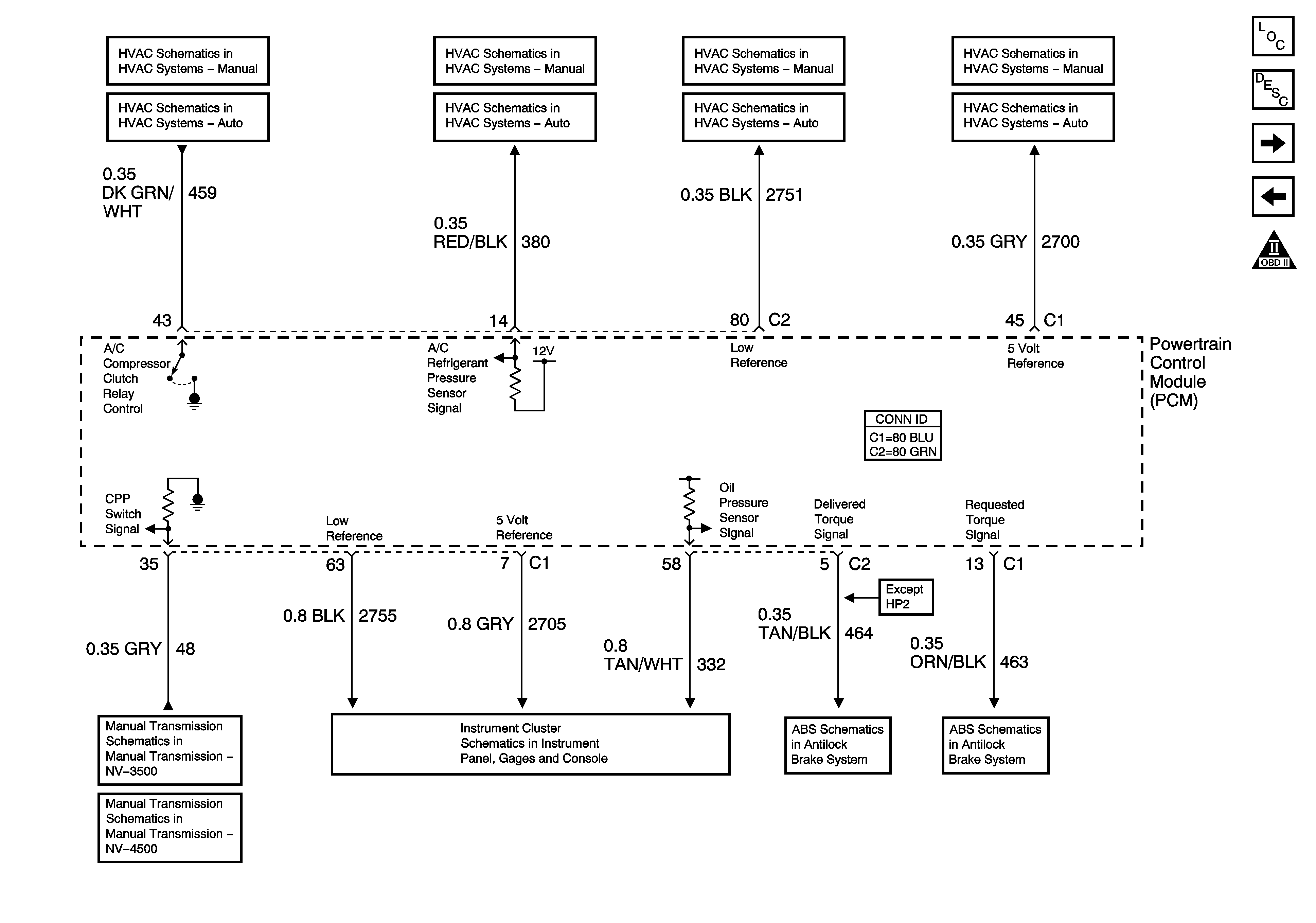

Object Number: 1226816  Size: FS
Master Electrical Component List
Powertrain Control Module Description
Controlled/Monitored Subsystem Schematics - 2 of 2
Fuel Controls - EVAP Controls and Fuel Tank Pressure
OBD II Symbol Description Notice
A/C Compressor Controls
Manual Transmission Schematics
Gages
8600 GVW or Less - 1 of 2
Figure 15:

Controlled/Monitored Subsystem References - 2 of 2
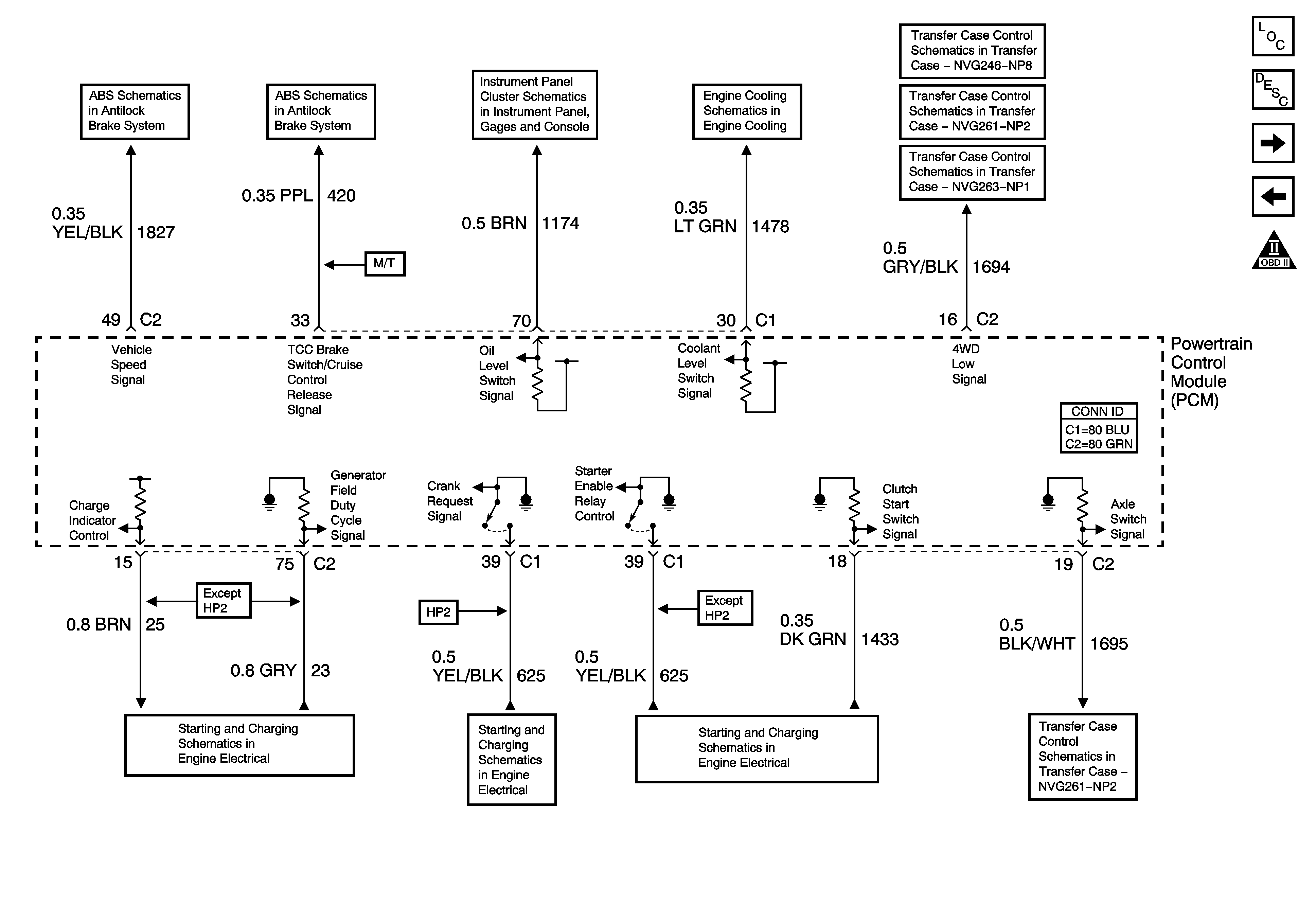

Object Number: 1226819  Size: FS
Master Electrical Component List
Powertrain Control Module Description
Transmission Controls - A/T - 4L60-E
Controlled/Monitored Subsystem Schematics - 1 of 2
OBD II Symbol Description Notice
8600 GVW or Less - 1 of 2
8600 GVW or Less - 2 of 2
Indicators
Coolant Level Indicator Control - Diesel and L18 Only
Power, Ground and Transfer Case Encoder Motor
Transfer Case Control Schematics
Power, Ground, Class 2 Serial Data and Transfer Case Encoder Motor
Charging - Gas
Starting - Gas
Engine Speed Signal and Accessory Battery Charging
Transfer Case Control Schematics
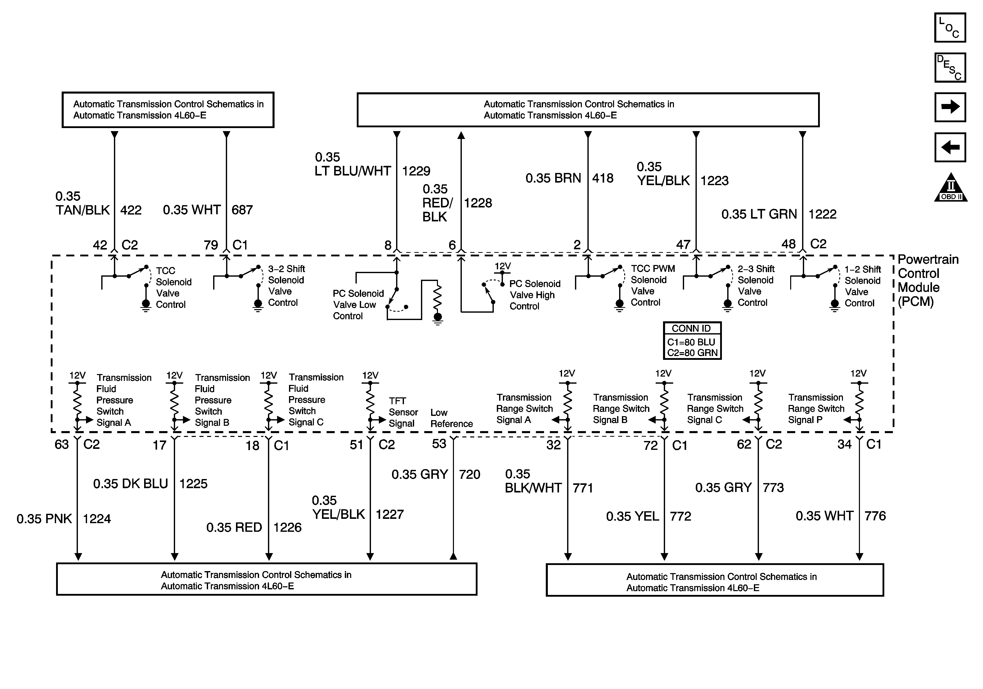
Figure 16:

Transmission Controls - A/T - 4L60-E


Object Number: 1226820  Size: FS
Master Electrical Component List
Powertrain Control Module Description
Transmission Controls - A/T - 4L80-E
Controlled/Monitored Subsystem Schematics - 2 of 2
OBD II Symbol Description Notice
Valve Controls and Brake Switch
Switch Inputs
Switch Inputs
Tow/Haul and PNP Switches
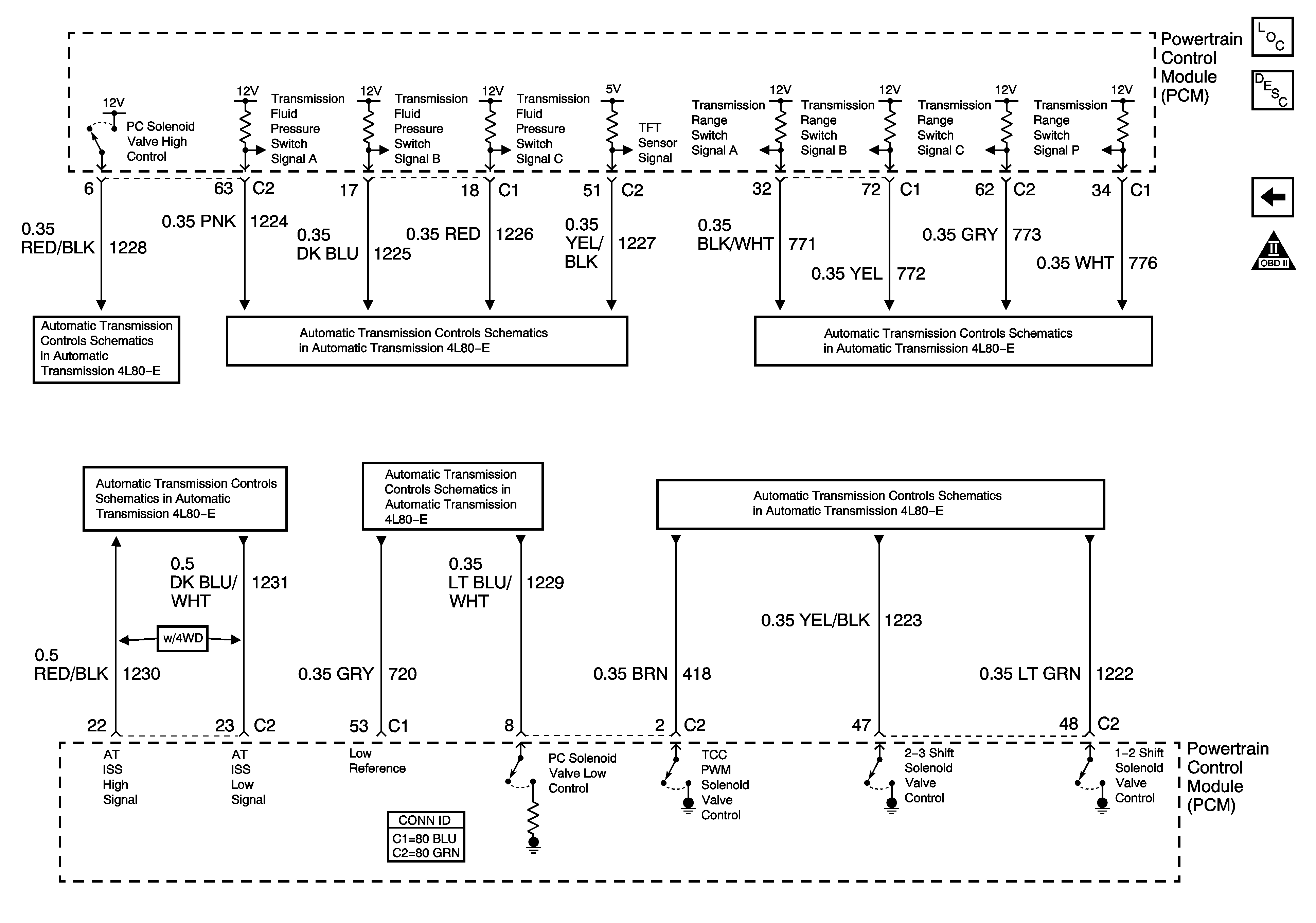
Figure 17:

Transmission Controls - A/T - 4L80-E


Object Number: 1226821  Size: FS
Master Electrical Component List
Powertrain Control Module Description
Transmission Controls - A/T - 4L60-E
OBD II Symbol Description Notice
Switch Inputs
Switch Inputs
Tow/Haul and PNP Switch Inputs
Switch Inputs
Switch Inputs
Valve Controls and Brake Switch