BINDING OR INOP IN REVERSE STUCK 4-3 SEQUENCE VALVE

SUBJECT: BINDING OR INOPERATIVE IN REVERSE, STUCK 4-3 SEQUENCE VALVE, AND/OR 2-3 SHIFT VALVE
MODELS: 1982-91 TRUCKS WITH 4L60 (700-R4) AUTOMATIC TRANSMISSIONS
THIS BULLETIN CANCELS AND REPLACES GMC TRUCK SERVICE BULLETIN 89-7A-115, DATED NOVEMBER, 1989 TO ADD 1991 MODEL YEAR TRUCKS AND INFORMATION CONCERNING THE BOLT TIGHTENING PATTERN. ALL COPIES OF 89-7A-115 SHOULD BE DISCARDED.
This bulletin covers service information for 1982 through 1991 HYDRA-MATIC 4L60 transmissions which may exhibit a binding in reverse condition. (The vehicle would feel as though the engine were being "brake torqued" if reverse range was selected.)
SERVICE PROCEDURE:
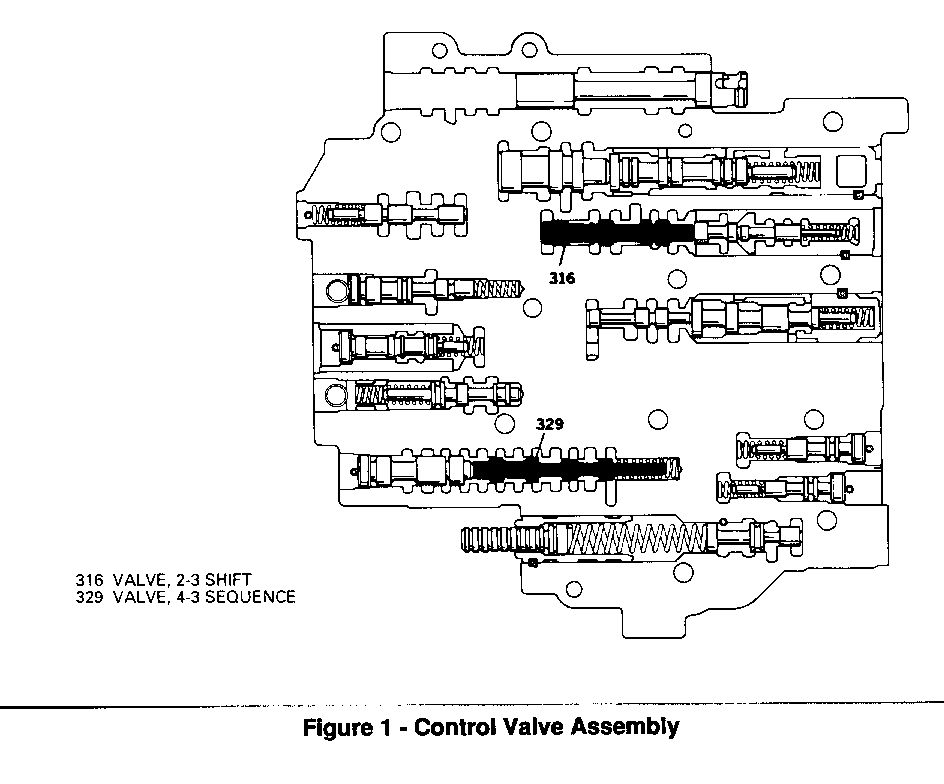
When servicing a HYDRA-MATIC 4L60 transmission for a binding in reverse condition, remove the control valve assembly and inspect the 4-3 sequence valve and the 2-3 shift valve. Refer to Figure 1. Either valve, if stuck in the upshifted position, will result in a binding condition. To correct this condition, the valve body must be completely disassembled and reconditioned according to procedures contained in the HYDRA-MATIC 4L60/THM 700-R4 Unit Repair section of the appropriate Service Manual.
Inspect the transmission bottom pan for clutch material or burned fluid. Evidence of this will necessitate further transmission diagnosis. Repairs may include complete transmission reconditioning, including disassembly and reconditioning of the transmission pump and possible torque converter replacement.
Complete the cleaning of the hydraulic circuit by changing the transmission fluid and filter and flushing the transmission cooler and cooler pipes.
[!] Important
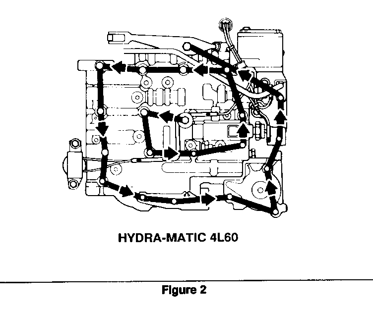
Overtorquing or uneven torquing of the bolts during unit reassembly can cause valves to bind. This condition may become more apparent as the unit warms to operating temperature. The correct bolt torque specifications for the HYDRA-MATIC 4L60 control valve assembly are 8-14 N-m (6-10 lb. ft.). Torquing bolts to the minimum specification, 8 N-m (6 lb. ft.) is recommended. The bolts should be tightened in a spiral pattern starting at the center and working toward the outside of the control valve assembly as shown in Figure 2.


General Motors bulletins are intended for use by professional technicians, not a "do-it-yourselfer". They are written to inform those technicians of conditions that may occur on some vehicles, or to provide information that could assist in the proper service of a vehicle. Properly trained technicians have the equipment, tools, safety instructions and know-how to do a job properly and safely. If a condition is described, do not assume that the bulletin applies to your vehicle, or that your vehicle will have that condition. See a General Motors dealer servicing your brand of General Motors vehicle for information on whether your vehicle may benefit from the information.
