DTC 24 Output Shaft Speed Sensor Circuit Low Input L57 MFI
Circuit Description
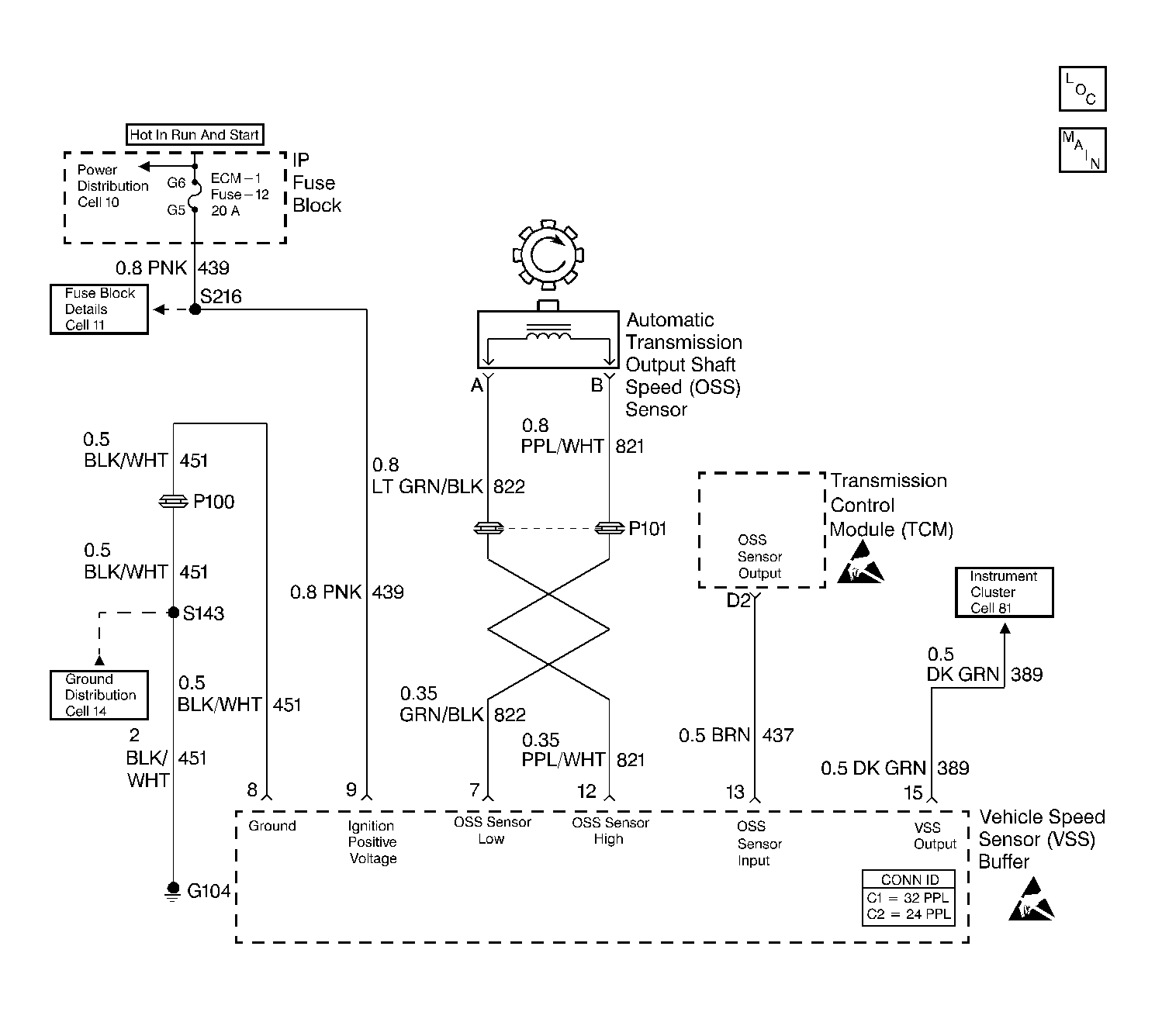
The speed sensor circuit consists of a magnetic induction type sensor, which is the output shaft speed (OSS) sensor, a vehicle speed sensor (VSS) buffer module, and wiring. Gear teeth pressed onto the output shaft carrier assembly induce an alternating voltage into the sensor. This signal transmits to the VSS buffer module. The VSS buffer module compensates for various final drive ratios. The VSS buffer module also converts the AC OSS sensor signal into a 40 pulse per revolution (PPR) 5 volt DC square wave form signal on circuit 437 to indicate transmission output speed.
When the transmission control module (TCM) detects a low output speed when the vehicle has a high engine speed in a drive gear range, then DTC 24 sets.
Conditions for Running the DTC
| • | No TP sensor DTC 21 or DTC 22. |
| • | No TFP manual valve position switch DTC 28. |
| • | The TP angle is 10-100%. |
| • | Circuit 437 voltage is constant. |
| • | Engine speed is greater than 3000 RPM. |
| • | The transmission is not in PARK or NEUTRAL. |
Conditions for Setting the DTC
| • | All the Conditions for Running the DTC are met for 3 seconds. |
| • | The OSS sensor speed is less than 200 RPM. |
Action Taken When the DTC Sets
| • | The TCM does not illuminate the MIL. |
| • | The TCM commands maximum line pressure. |
| • | The TCM commands 2nd gear. |
| • | The TCM stores DTC 24 in TCM history. |
Conditions for Clearing the DTC
| • | A scan tool clears the DTC from TCM history. |
| • | The TCM clears the DTC from TCM history if the vehicle completes 40 consecutive key cycles without a diagnostic fault occurring. |
| • | The TCM cancels the DTC default actions when the fault no longer exists, and the ignition switch is OFF long enough in order to power down the TCM. |
Diagnostic Aids
| • | Inspect the wiring at the TCM, the A/T OSS and the VSS buffer module connectors and all other circuit connecting points for the following conditions: |
| - | A backed out terminal |
| - | A damaged terminal |
| - | Reduced terminal tension |
| - | A chafed wire |
| - | A broken wire inside the insulation |
| - | Moisture intrusion |
| - | Corrosion |
| • | When diagnosing for an intermittent short or open, massage the wiring harness while watching the test equipment for a change. It may be necessary to drive the vehicle. |
| • | Inspect the speed sensor wiring for contact with sharp metal edges. |
Test Description
The numbers below refer to the step numbers on the diagnostic table.
-
This step verifies the fault condition.
-
This step tests sensor integrity.
-
This step verifies power and ground to the VSS buffer module.
-
This step verifies the TCM input controlled by the speed buffer.
Step | Action | Value(s) | Yes | No |
|---|---|---|---|---|
1 | Was the Powertrain On-Board Diagnostic (OBD) System Check performed? | -- | ||
Important:: Before clearing the DTCs, use the scan tool in order to record the Failure Records. Using the Clear Info function erases the Failure Records from the TCM. Does the Transmission OSS increase with the drive wheel speed? | -- | Go to Diagnostic Aids | ||
Is the voltage greater than the specified value? | 2.0 volts at 2000 RPM | |||
4 |
Is the voltage greater than the specified value? | 2.0 volts AC at 2000 RPM | ||
5 |
Refer to General Electrical Diagnosis in Wiring Systems. Was a condition found? | -- | ||
6 |
Refer to General Electrical Diagnosis in Wiring Systems. Was a condition found? | -- | Go to Diagnostic Aids | |
7 |
Is the voltage greater than the specified value? | 10.5 volts DC | ||
8 | Inspect the ignition feed circuit 439 (PNK) for an open. Refer to General Electrical Diagnosis in Wiring Systems. Was a condition found? | -- | -- | |
With the ignition switch in the RUN position, measure the voltage between terminals 8 and 9 of the VSS buffer connector. Is the voltage greater than the specified value? | 10.5 volts DC | |||
10 | Inspect the VSS buffer module ground circuit 451 (BLK/WHT) for an open. Refer to General Electrical Diagnosis in Wiring Systems. Was a condition found? | -- | -- | |
11 | With the connector off the speed buffer, and the ignition switch in the RUN position, measure the voltage between terminal 13, of the VSS buffer harness connector, and a good ground. Is the voltage within the specified value? | 4.8-5.2 volts DC | ||
12 | Is the voltage in Step 11 greater than the specified voltage? | 5.2 volts DC | ||
13 | Inspect circuit 437 (BRN) for a short to power. Refer to General Electrical Diagnosis in Wiring Systems. Was a condition found? | -- | ||
14 | Inspect circuit 437 (BRN) for a short to power. Refer to General Electrical Diagnosis in Wiring Systems. Was a condition found? | -- | ||
Is the voltage within the specified values? | 1.5 - 3.5 volts DC | |||
16 | Repair the wiring as necessary. Refer to Wiring Repairs in Wiring Systems. Is the repair complete? | -- | -- | |
17 | Replace the OSS sensor. Refer to Vehicle Speed Sensor Replacement . Is the replacement complete? | -- | -- | |
18 | Replace the VSS buffer module. Refer to Vehicle Speed Signal Buffer Replacement in Engine Controls. Is the replacement complete? | -- | -- | |
19 | Replace the TCM. Refer to Powertrain Control Module Replacement/Programming in Engine Controls. Is the replacement complete? | -- | -- | |
20 | Perform the following procedure in order to verify the repair:
Does the Scan Tool display an output speed greater than 500 RPM for 1 second? | -- | System OK |
