DTC P0502 Vehicle Speed Sensor (VSS) Circuit Low Input L29/L31/L35
Circuit Description
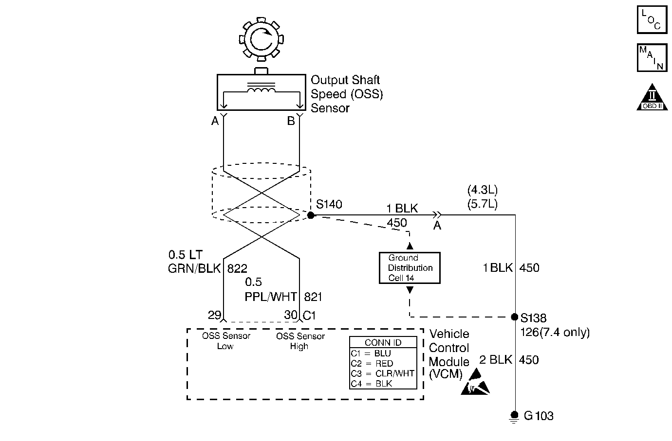
The output shaft speed sensor (OSS sensor), which is a permanent magnet (PM) generator, provides the vehicle speed information to the vehicle control module (VCM). The PM generator produces a pulsing AC voltage as the transmission speed sensors rotor teeth pass through the sensor's magnetic field. The AC voltage level and the number of pulses increase as the speed of the vehicle increases. The VCM then converts the pulsing voltage to a digital signal for vehicle speed. The vehicle speed is used for engine and transmission calculations.
If the VCM detects a low vehicle speed and there is a high engine speed in a drive gear range, DTC P0502 sets. DTC P0502 is a type D DTC. For California emissions, DTC P0502 is a type B DTC.
Conditions for Running the DTC
| • | No mass air flow (MAF) sensor DTCs P0101, P0102 or P0103. |
| • | No MAP DTCs P0106, P0107 or P0108. |
| • | No throttle position (TP) sensor DTCs P0122 or P0123. |
| • | No TFP manual valve position switch DTC P1810. |
| • | No A/T ISS sensor DTC P0716 or P0717. |
| • | The engine torque must be 108 N·m (80 lb ft) to the following: |
| - | 406 N·m (300 lb ft) 4.3L |
| - | 542 N·m (400 lb ft) 5.7L |
| - | 677 N·m (500 lb ft) 7.4L |
| • | The A/T ISS is greater than 1500 RPM. |
| • | The gear range is not PARK or NEUTRAL. |
| • | TP angle is greater than 10%. |
| • | The engine is running more than 475 RPM for more than 7 seconds. |
Conditions for Setting the DTC
The OSS is less than 50 RPM for at least 4 seconds.
Action Taken When the DTC Sets
| • | For California emissions, the VCM illuminates the malfunction indicator lamp (MIL). |
| • | The VCM commands maximum line pressure. |
| • | The VCM freezes the shift adapts. |
| • | The VCM defaults a calculated output speed value by using the ISS values. |
| • | The VCM stores DTC P0502 in VCM history. |
Conditions for Clearing the MIL/DTC
| • | For California emissions, the VCM turns OFF the MIL during the third consecutive trip in which the diagnostic test runs and passes. |
| • | A scan tool clears the DTC from VCM history. |
| • | For California emissions, the VCM clears the DTC from VCM history if the vehicle completes 40 consecutive warm-up cycles without an emission related diagnostic fault occurring. |
| • | For Federal emissions, the VCM clears the DTC from VCM history if the vehicle completes 40 consecutive warm-up cycles without a non-emission related diagnostic fault occurring. |
| • | The VCM cancels the DTC default actions when the fault no longer exists and the ignition switch is OFF long enough in order to power down the VCM. |
Diagnostic Aids
| • | DTC P0502 sets when no vehicle speed is detected at the start off. |
| • | Inspect the wiring at the VCM, the OSS sensor connector and all other circuit connecting points for the following conditions: |
| - | A backed out terminal |
| - | A damaged terminal |
| - | Reduced terminal tension |
| - | A chafed wire |
| - | A broken wire inside the insulation. |
| - | Moisture intrusion |
| - | Corrosion |
| • | When diagnosing for an intermittent short or open, massage the wiring harness while watching the test equipment for a change. |
| • | First diagnose and clear any engine DTCs or TP sensor codes. Then inspect for any transmission DTCs that may have reset. |
Test Description
The numbers below refer to the step numbers on the diagnostic table.
-
This step tests for voltage in the 822 low circuit.
-
This step tests the 5-volt and ground circuit of the VCM.
-
This step tests the integrity of the OSS sensor.
-
This step tests the OSS circuit.
Step | Action | Value(s) | Yes | No |
|---|---|---|---|---|
1 | Was the Powertrain On-Board Diagnostic (OBD) System Check performed? | -- | Go to Powertrain On Board Diagnostic (OBD) System Check (4.3L) or Powertrain On Board Diagnostic (OBD) System Check (5.7L) or Powertrain On Board Diagnostic (OBD) System Check (7.4L) | |
2 |
Important: Before clearing the DTCs, use the scan tool in order to record the Freeze Frame and Failure Records. Using the Clear Info function erases the Freeze Frame and Failure records from the VCM. Ensuring that the drive shaft is rotating, does the Transmission OSS increase with the drive wheel speed? | -- | Go to Diagnostic Aids | |
3 |
Is the voltage within the specified value? | 4.0-5.1 volts DC | ||
With the ignition switch in the RUN position, measure the voltage between terminal B of the OSS sensor harness connector and a good ground. Is the voltage less than the specified value? | 0.2 volts | |||
5 | Was the voltage reading in Step 3 greater than the specified value? | 5.1 volts | ||
With the ignition switch in the RUN position, measure the voltage between terminals A and B of the OSS sensor harness connector. Is the voltage within the specified value? | 4.0-5.1 volts | |||
7 |
Refer to General Electrical Diagnosis in Wiring Systems. Refer to Wiring Repairs in Wiring Systems. Was the condition found? | -- | ||
8 |
Refer to Wiring Repairs in Wiring Systems. Was the condition found? | -- | ||
9 |
Refer to Wiring Repairs in Wiring Systems. Was the condition found? | -- | ||
10 | Using the J 39200 DMM, measure the resistance between terminals A and B of the OSS sensor. Is the resistance within the specified value? | 1042-2088ohms | ||
Is the voltage greater than the specified value? | 0.5 volts AC | |||
12 |
Refer to General Electrical Diagnosis in Wiring Systems. Refer to General Electrical Diagnosis in Wiring Systems. Refer to General Electrical Diagnosis in Wiring Systems. Refer to Wiring Repairs in Wiring Systems. Was the condition found? | -- | ||
Is the voltage greater than the specified value? | 0.5 volts AC | -- | ||
14 | Inspect the VCM pins and C1 terminals for corrosion or reduced terminal tension. Was the condition found? | -- | ||
15 |
Refer to Unit Repair. Was the condition found? | -- | ||
16 | Replace the VCM. Refer to VCM Replacement/Programming (4.3L) or VCM Replacement/Programming (5.7L) or VCM Replacement/Programming (7.4L) in Engine Controls. Is the replacement complete? | -- | -- | |
17 | Replace the OSS sensor. Refer to Vehicle Speed Sensor Replacement . Is the replacement complete? | -- | -- | |
18 | Perform the following procedure in order to verify the repair:
Has the test run and passed? | -- | System OK |
