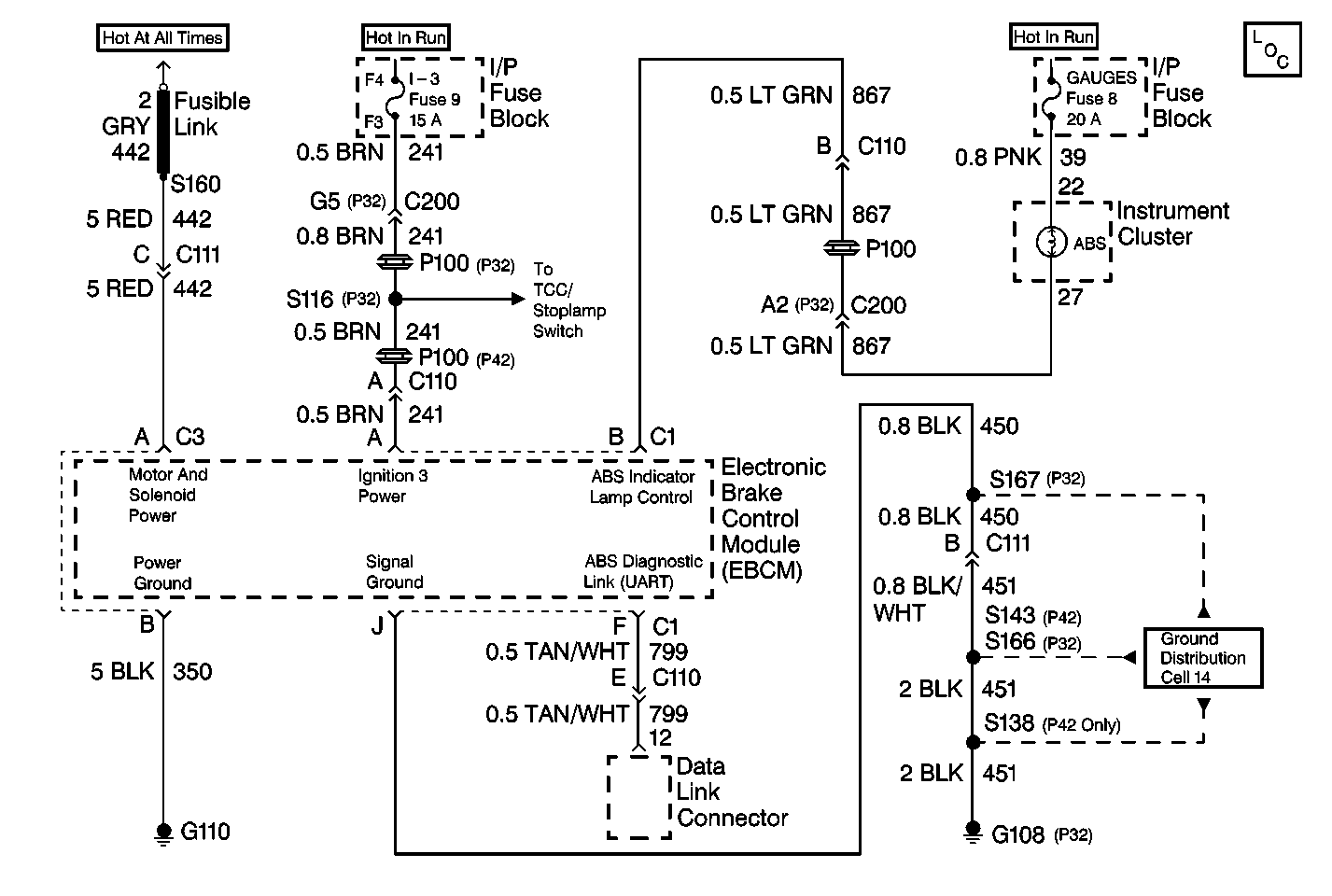
System Description
The diagnostic system check is an organized approach to identifying an Antilock Brake System (ABS) malfunction. The diagnostic system check must be the starting point for any ABS complaint diagnosis. The diagnostic system check directs the service technician to the next logical step in diagnosing the complaint.
Diagnostic serial data is transmitted/received by the EBCM 10-way terminal F. The EBCM is supplied switched ignition voltage through the EBCM 10-way terminal A, and signal ground is provided through the EBCM 10-way terminal J.
Diagnostic Aids
Excessive resistance in the signal ground or ignition power circuit will not allow communication with the EBCM. If communication with the EBCM is not possible, ensure that the ABS signal ground connection is good and that there is no excessive resistance in the ignition power circuit.
Test Description
The numbers below refer to the steps in the diagnostic table:
-
This step checks for normal ABS indicator lamp operation.
-
This step checks for ignition voltage at the EBCM.
-
This step checks for high resistance in the ground circuit.
-
This step checks for high resistance in the ignition voltage circuit.
-
This step checks for a short to ground in the ignition voltage circuit.
Step | Action | Value(s) | Yes | No |
|---|---|---|---|---|
1 |
Is data being received from the EBCM? | -- | ||
2 | Using the Scan Tool , check for any DTCs. Are any current or history DTCs displayed? | -- | Go to Appropriate DTC Table | |
Did the ABS indicator lamp turn on for three seconds and then turn off? | -- | System is operating normally. Go to Diagnostic Aids. | ||
Is the voltage measured within the specified range? | 10-15V | |||
Caution: Unless directed otherwise, the ignition and start switch must be in the OFF or LOCK position, and all electrical loads must be OFF before servicing any electrical component. Disconnect the negative battery cable to prevent an electrical spark should a tool or equipment come in contact with an exposed electrical terminal. Failure to follow these precautions may result in personal injury and/or damage to the vehicle or its components. Is the resistance measured within the specified range? | 0-2ohms | |||
6 |
Is the terminal contact or the connection poor? | -- | ||
7 | Replace the terminals or repair the poor connection. Is the repair complete? | -- | -- | |
8 | Reconnect the EBCM connectors and the battery cables. Are the EBCM connectors and the battery cables reconnected? | -- | Go to Wiring Systems (Cell 50) for serial data circuit diagnosis | -- |
Is the resistance measured within the specified range? | 0-2ohms | |||
Is the resistance measurement equal to the specified value? | OL | |||
11 | Observe the ABS indicator lamp. Does the ABS indicator lamp stay on? | -- | Go to ABS Indicator Always On | |
12 | Repair open or high resistance in CKT 451. Is the repair complete? | -- | -- | |
13 |
Is the repair complete? | -- | -- | |
14 |
Is the repair complete? | -- | -- | |
15 | Inspect CKT 241 and the 10-way EBCM harness connector for physical damage which may result in a short to ground with the 10-way EBCM harness connector connected to the EBCM. Is there evidence of damage? | -- | ||
16 | Repair the terminals which are damaged. Is the repair complete? | -- | -- | |
17 |
Is the repair complete? | -- | -- |
