Tools Required
J 39400 Electronic
Leak Detector
Caution: Do not operate the detector in a combustible atmosphere since its sensor
operates at high temperatures or personal injury and/or damage to the equipment
may result.
Important: Halogen leak detectors are sensitive to windshield washing solutions,
many solvents, cleaners, and some adhesives used in the vehicle. Ensure that
the surfaces are clean and dry in order to prevent a false warning. The ingestion
of liquids will damage the detector.
Perform a refrigerant leak test when the following conditions exist:
| • | After performing a service operation which disturbs the following
items: |
Many methods and special tools are available for use in order to perform
the refrigerant leak test. No matter which tool is used, carefully perform
the test.

The electronic leak detector is the most useful tool in locating refrigerant
leaks. The J 39400
Electronic
Leak Detector is a small unit that operates on a 12V DC. This unit
produces an audible signal that increases in frequency as R-134a is detected.
Ensure that the instrument is properly calibrated according to the instructions.
Ensure the detector is in the proper setting for the type of refrigerant
being tested. Place the detector GAS switch in the R-134a setting prior
to use.

The most common leaks are found at the refrigerant fittings or the connections.
The following conditions may cause the leaks:
| • | Lack of lubricant on the O-ring seals |
| • | Dirt or debris across the O-ring seals |
Even the smallest piece of lint from cotton gloves or shop cloths may
create a leak path across an O-ring seal.
The successful use of this and any other electronic detector depends
greatly upon the scan rate. Carefully follow the manufacturer's instructions
regarding the following items:
Important: Always follow the refrigerant system around in a continuous path in
order to avoid missing any areas of potential leaks. Always test all areas
in order to ensure that the entire system is leak free, even when one leak
is already found.
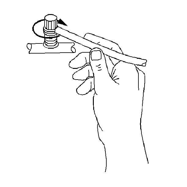
Circle each joint completely by moving at 25-51 mm (1-2 in)
per second with the tip of the probe as close to the surface as possible.
Circle the joint no more than 6 mm (0.25 in) away. Do not block
the air intake. The audible tone will go from a steady 1-2 clicks
per second to a solid alarm to indicate a leak. Frequently adjust the balance
knob in order to maintain the 1-2 clicks per second rate.
Use this procedure in order to test the following components:
| • | The air conditioning (A/C) evaporator inlet |
| • | The A/C evaporator outlet |
| • | The A/C accumulator inlet |
| • | The A/C accumulator outlet |
| • | The A/C condenser inlet |
| • | The A/C condenser outlet |
| • | Any area that shows signs of damage |
| • | The A/C compressor rear head |
Service Ports/Access Valves
The primary seal for the service ports is the sealing cap. The cap contains
a specially designed O-ring seal or gasket that provide a leak-free seal.
A loss of refrigerant charge will result if the following conditions exist:
Air Conditioning (A/C) Evaporator Core
One of the most difficult leaks to find is in the air conditioning (A/C)
evaporator core. Use the following procedure in order to leak test the core:
- Turn the blower fan on high for 15 or more seconds.
- Turn the blower fan off.
- Wait for 10 minutes.
- Remove the blower motor resistor.
- Insert the leak detector probe as close to the A/C evaporator
as possible. A leak is detected if the detector goes to a solid alarm.
- If possible, visually inspect the core face with a flashlight
for evidence of refrigerant oil.
Air Conditioning (A/C) Compressor Block Fitting and Shaft Seal
- Blow shop air behind and in front of the air conditioning (A/C)
compressor clutch/pulley for at least 15 seconds.
- Wait for 1-2 minutes.
- Probe the area in front of the pulley.
A leak is detected if the detector goes to a solid alarm.
When Leak Cannot Be Found
Tools Required
| • | J 39500-B R-134a
A/C Refrigerant Recovery, Recycling, and Recharging Station (ACR4) |
Use the following diagnostic procedure when an air conditioning (A/C)
refrigerant leak cannot be found using a J 39400
leak detector.
- Make a copy of Attachment 1 (Service Information Form).
- Use the J 39500-B
and record the necessary information.
- Recover the existing R-134a refrigerant and record the refrigerant
weight.
- Add J 41447
or GM P/N 12346303, using the J 41459
.
- Re-charge the system following the procedures in Section 1B
of the Service Manual.
Important: R-134a florescent dye will remain in the lubricant for the life of the
vehicle as long as the vehicle's A/C system has not been flushed. If no leaks
are found, return the vehicle to the customer. Advise the customer of the
dye in the system and that the system may need to be rechecked at a later
date. Attach the Service Information Form to the Warranty Repair Order
when completed.
- Test the system for leaks using a high intensity black light or GM P/N 12377979.


