Fan Clutch Replacement Diesel
Tools Required
J 41240-5A Fan Clutch Wrench
Removal Procedure
- Remove the upper fan shroud. Refer to Engine Coolant Fan Upper Shroud Replacement .
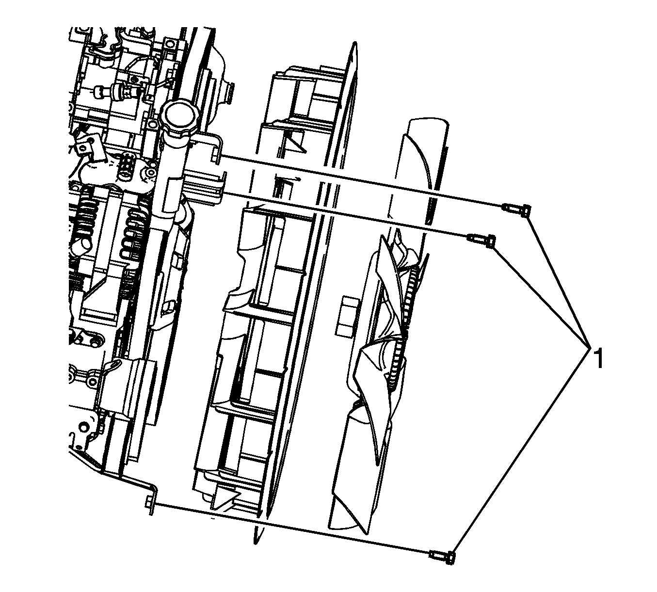
- Remove the 3 engine cooling fan shroud bolts (1).
- Position the engine cooling fan shroud (1) forward to the radiator.
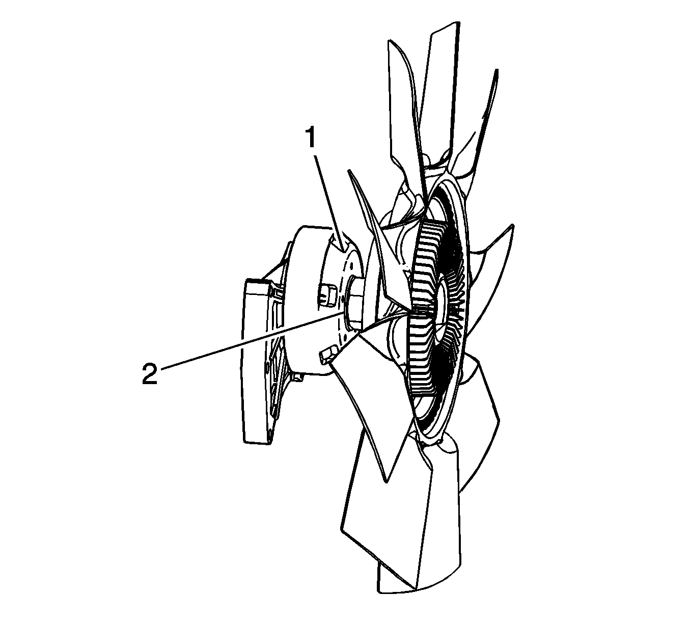
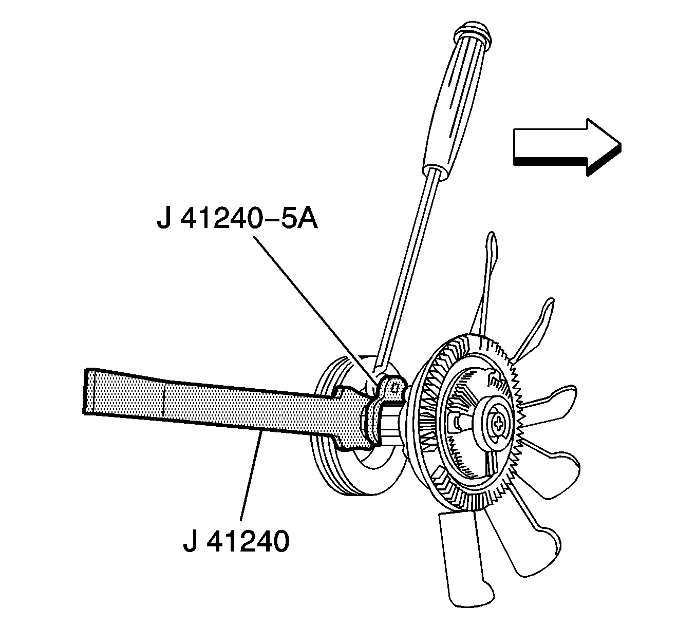
- Install a long pin bar into the fan hub (1).
- Use a J 41240-5A to remove the fan hub nut (2) from the hub in a counterclockwise rotation.
- Remove the fan and the engine cooling fan shroud as an assembly.
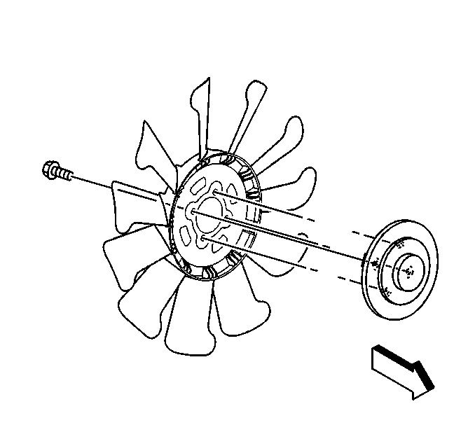
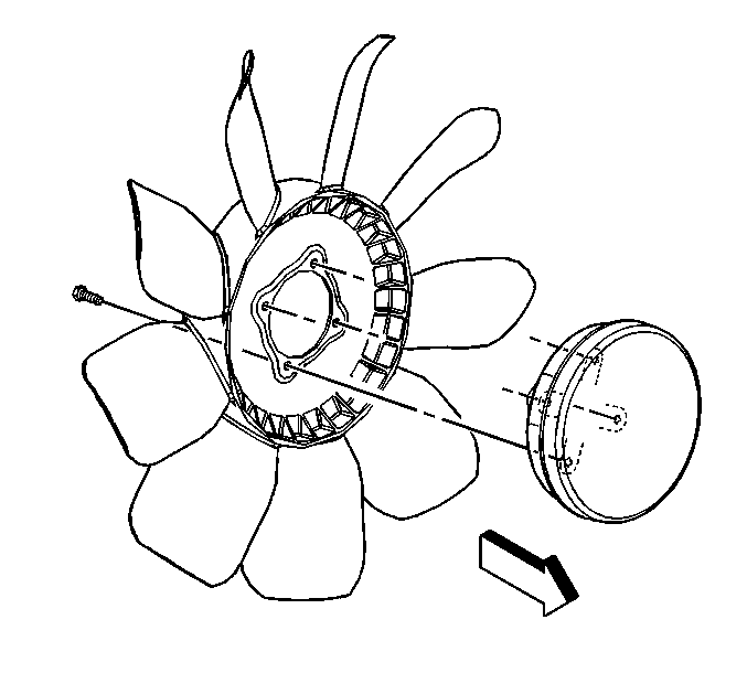
- Remove the fan clutch bolts from the rear of the fan blade.
- Separate the fan clutch from the fan blade.
Installation Procedure
Caution: Do not use or attempt to repair a damaged cooling fan assembly. Replace damaged fans with new assemblies. An unbalanced cooling fan could fly apart causing personal injury and property damage.
- Install the fan clutch onto the fan blade.
- Install the fan clutch bolts.
- Install the fan and engine cooling fan shroud assembly to the fan hub.
- Use a J 41240-5A on the fan clutch hub nut (2) to install a long pry bar to the fan clutch hub (1).
- Position the engine cooling fan shroud on the 3 mounting brackets (1).
- Install the bolts. Loosely tighten the top mounting bolt at the oil filler neck.
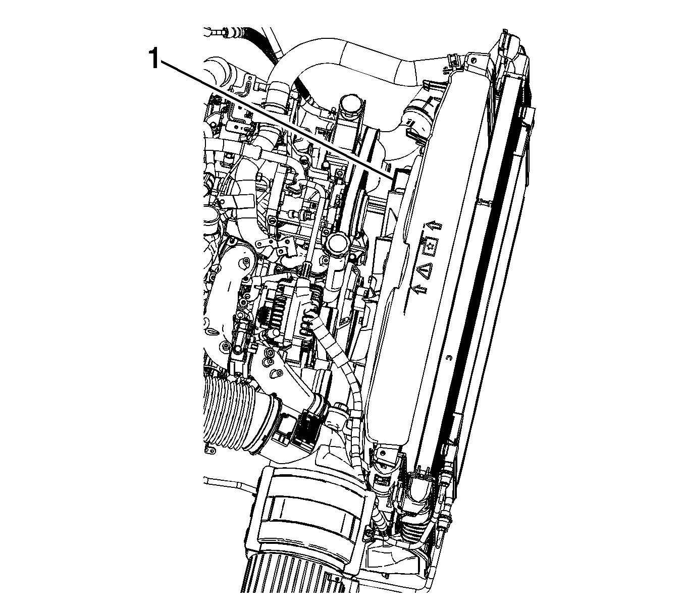
- Center the engine cooling fan shroud to the fan blade in 3 places (1).
- Make sure the orientation of the cooling fan shroud (1) and rubber seal (2) are installed correctly
- Fully tighten the 3 engine cooling fan shroud bolts (1).
- Install the upper fan shroud. Refer to Engine Coolant Fan Upper Shroud Replacement .
Notice: Use the correct fastener in the correct location. Replacement fasteners must be the correct part number for that application. Fasteners requiring replacement or fasteners requiring the use of thread locking compound or sealant are identified in the service procedure. Do not use paints, lubricants, or corrosion inhibitors on fasteners or fastener joint surfaces unless specified. These coatings affect fastener torque and joint clamping force and may damage the fastener. Use the correct tightening sequence and specifications when installing fasteners in order to avoid damage to parts and systems.
Tighten
Tighten the bolts to 23 N·m (17 lb ft).

Tighten
Tighten the nut clockwise to 56 N·m (41 lb ft).

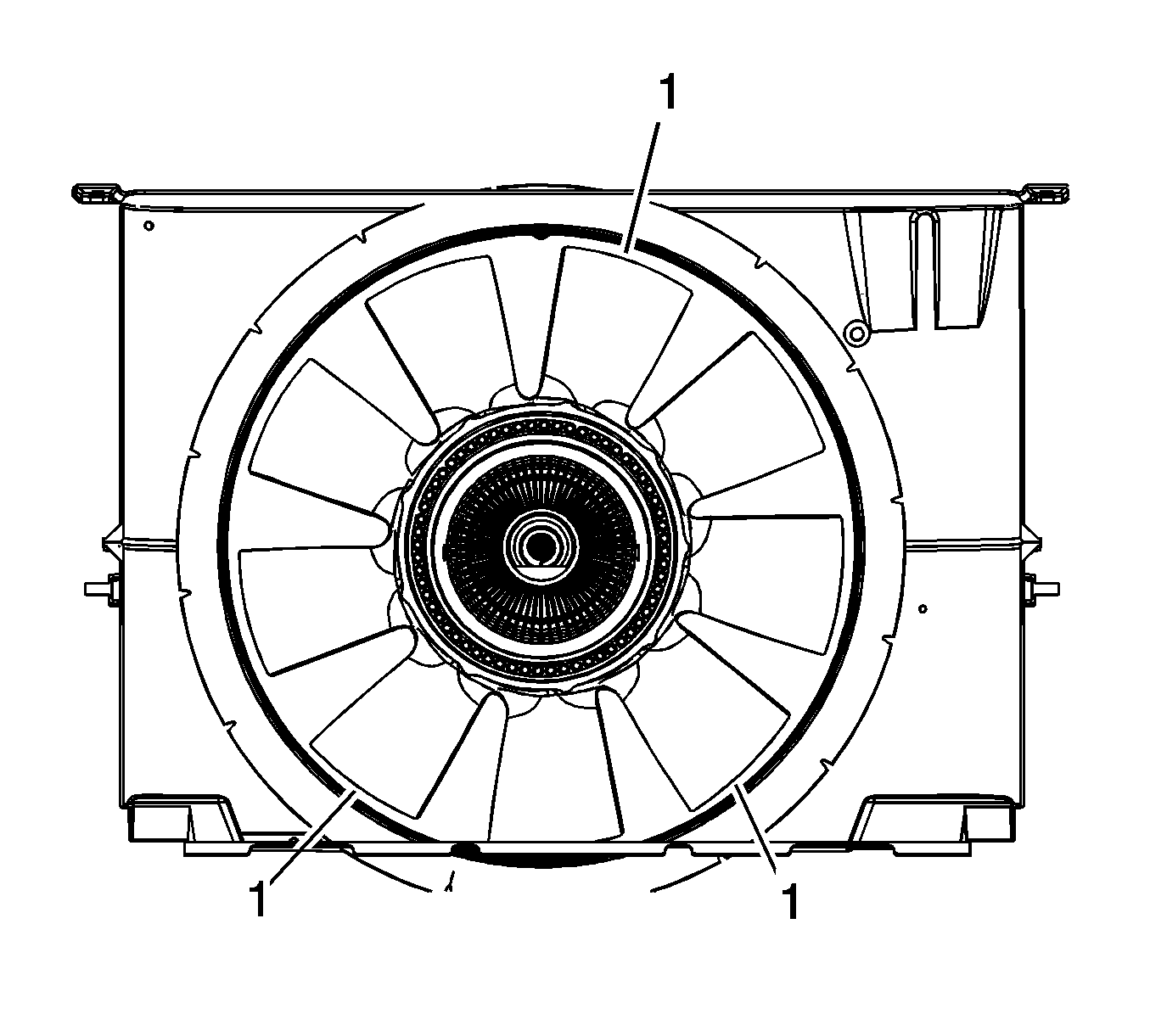
Important: Maintain a 6 mm (0.25 in) minimum clearance at all 3 places.
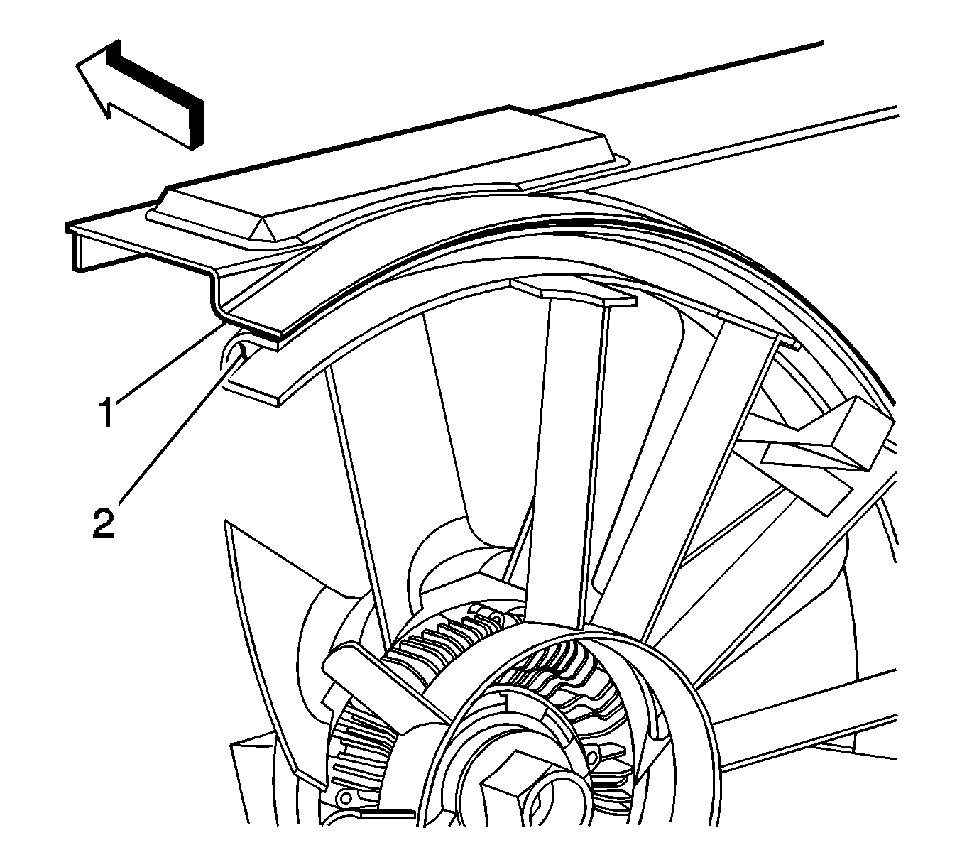
Important: Improper installation could cause damage to the fan and shroud while vehicle is in service.

Tighten
Tighten the bolts to 8 N·m (71 lb in).
Fan Clutch Replacement Gasoline
Tools Required
J 46406 Fan Clutch Remover and Installer
Removal Procedure
- Remove the upper fan shroud. Refer to Engine Coolant Fan Upper Shroud Replacement .
- Install the J 46406 to the fan clutch.
- Remove the fan hub nut from the water pump in a counterclockwise rotation.
- Remove the fan clutch bolts from the rear of the fan blade.
- Separate the fan clutch from the fan blade.
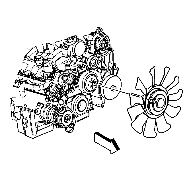

Installation Procedure
- Install the fan clutch bolts from the rear of the fan blade.
- Install the fan clutch bolts.
- Install the fan assembly.
- Install the J 46406 to the fan clutch.
- Install the upper fan shroud. Refer to Engine Coolant Fan Upper Shroud Replacement .

Notice: Use the correct fastener in the correct location. Replacement fasteners must be the correct part number for that application. Fasteners requiring replacement or fasteners requiring the use of thread locking compound or sealant are identified in the service procedure. Do not use paints, lubricants, or corrosion inhibitors on fasteners or fastener joint surfaces unless specified. These coatings affect fastener torque and joint clamping force and may damage the fastener. Use the correct tightening sequence and specifications when installing fasteners in order to avoid damage to parts and systems.
Tighten
Tighten the bolts to 23 N·m (17 lb ft).


Tighten
Tighten the nut clockwise to 56 N·m (41 lb ft).
