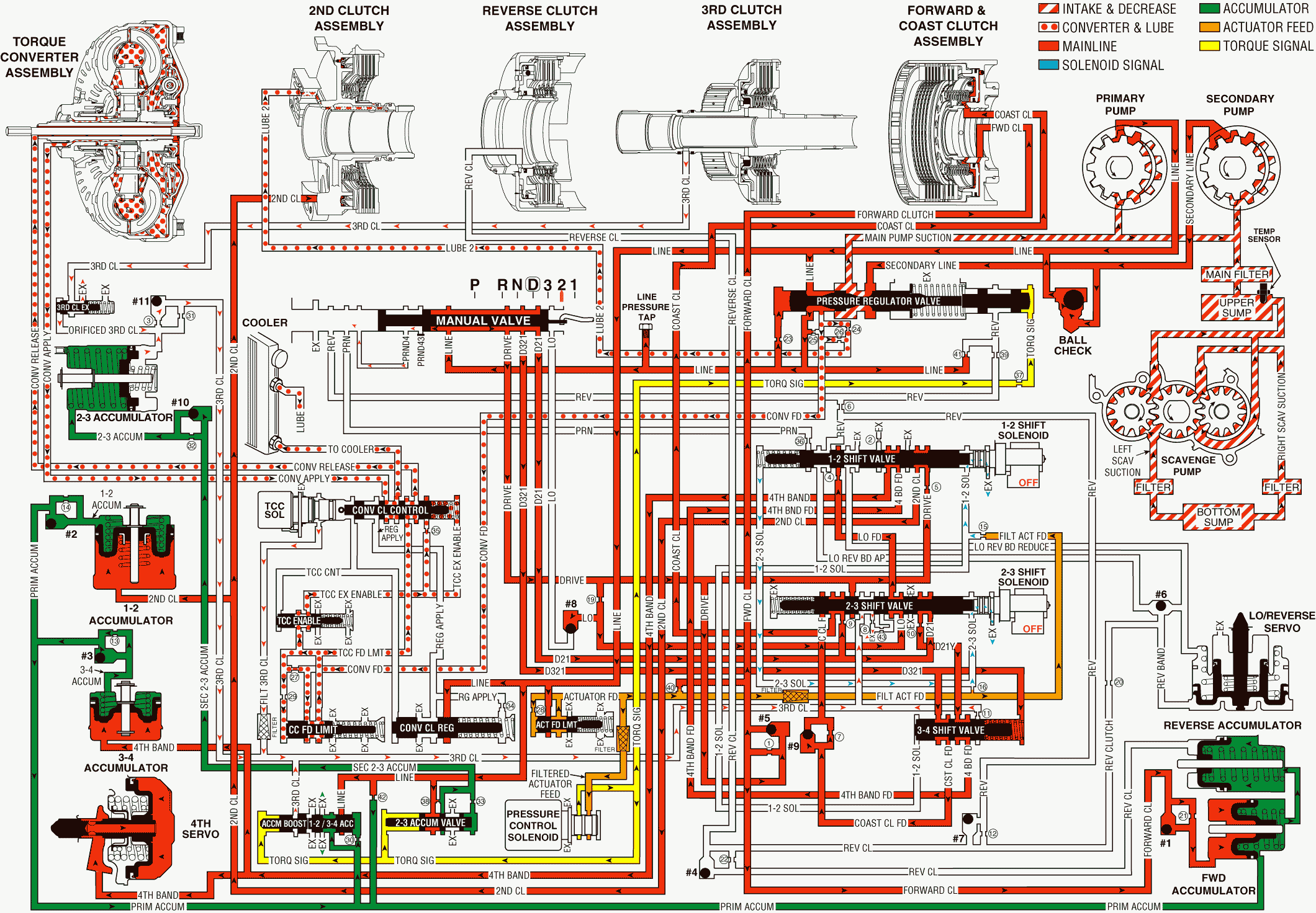
When the gear selector lever is moved to the Manual Second (D2) gear range, the manual valve moves and allows line pressure to enter the D21 fluid passage. The transmission reacts by shifting immediately into second gear range. The transmission is prevented from upshifting into either Third or Fourth gear.
Fourth Band Applies
Manual Valve
Line pressure at the valve enters the D21 fluid circuit which is then routed to the 2-3 shift valve.
2-3 Shift Solenoid (SS) Valve
The 2-3 SS valve de-energizes (turns OFF) in order to allow fluid from the 2-3 SS valve to exhaust through the solenoid. In the absence of 2-3 SS valve fluid pressure at the 2-3 shift valve, spring force acting on the end of the valve moves the valve into the downshifted position .
2-3 Shift Valve
Spring force hold the 2-3 shift valve in the downshifted position. D21 fluid passes through the valve and orifice #10, where the fluid enters the orificed D21Y circuit. Orificed D21Y fluid is then routed to the 3-4 shift valve. D21 fluid also passes through orifice #9, where the fluid enters the coast clutch circuit, and the fluid is routed to the 3-4 shift valve. Coast clutch fluid is then directed to the coast clutch piston, and the fluid applies the clutch.
3-4 Shift Valve
Spring force and D321 fluid hold the 3-4 shift valve in the downshifted position. The 3-4 shift valve allows orificed D21Y fluid to enter the fourth band feed circuit. Fourth band feed is then routed to the 1-2 shift valve.
1-2 Shift Valve
Spring force holds the 1-2 shift valve in the upshifted position. The 1-2 shift valve allows fourth band feed fluid to enter the fourth band circuit.
3-4 Accumulator Assembly
Fourth band fluid is routed to the 3-4 accumulator piston. The fluid actuates the piston during the apply of the fourth band assembly.
Third Clutch Releases
2-3 Shift Valve
Spring force holds the 2-3 shift valve in the downshifted position. The 2-3 shift valve prevents drive fluid from entering the third clutch circuit. In the absence of hydraulic pressure in the third clutch circuit, spring force moves the third clutch exhaust valve.
Third Clutch Exhaust Valve
Spring force holds the third clutch exhaust valve in the downshifted position. The valve allows third clutch fluid from the third clutch piston to exhaust through the valve. Orificed third clutch fluid form the valve is routed back through orifice #3 to checkball #11.
#11 Checkball (Third Clutch, Orificed Third Clutch)
The #11 checkball is located in the case cover. This checkball is unseated by orificed third clutch fluid. This allows fluid to enter the third clutch fluid circuit.
2-3 Accumulator
Orificed third clutch fluid from the accumulator piston passes through orifice #31, and the fluid enters the third clutch circuit. Third clutch fluid is then routed to the 2-3 shift valve and to the TCC solenoid valve, where the fluid exhausts.
Manual Second Gear

