Exhaust Manifold Replacement - Right Side 4.8L, 5.3L, and 6.0L Engines
- Raise and suitably support the vehicle. Refer to Lifting and Jacking the Vehicle .
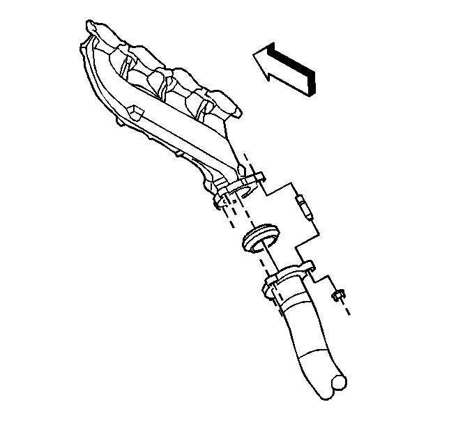
- Remove the exhaust manifold pipe nuts.
- Lower the vehicle.
- Remove the oil level indicator tube. Refer to Oil Level Indicator and Tube Replacement .
- Remove the spark plugs. Refer to Spark Plug Replacement .
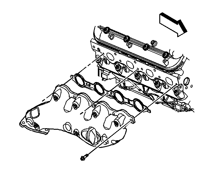
- Remove the exhaust manifold bolts, manifold, and gasket.
- Discard the gasket.
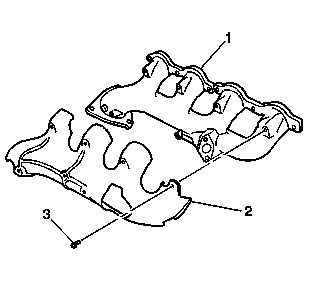
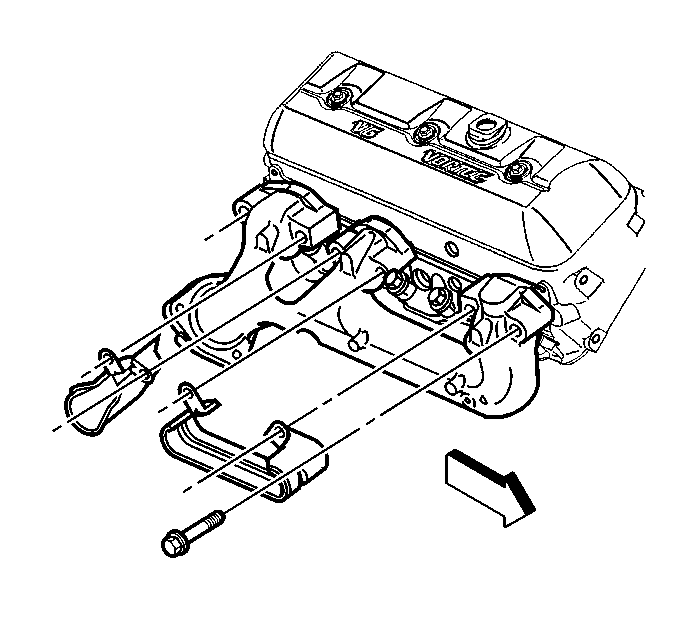
- Remove the heat shield bolts (1), and shield (2) from the exhaust manifold (1), if necessary.
- Clean and inspect the exhaust manifold. Refer to Exhaust Manifold Cleaning and Inspection .
Installation Procedure
- Install the heat shield (2), and bolts (1) to the exhaust manifold (1), if necessary.
- Apply a 5 mm (0.2 in) wide band of threadlock GM P/N 12345493 (Canadian P/N 10953488), or equivalent to the threads of the exhaust manifold bolts.
- Install the exhaust manifold, NEW gasket and bolts.
- Tighten the bolts a first pass to 15 N·m (11 lb ft). Tighten the bolts beginning with the center 2 bolts. Alternate from side-to-side, and work toward the outside bolts.
- Tighten the bolts a final pass to 25 N·m (18 lb ft). Tighten the bolts beginning with the center 2 bolts. Alternate from side-to-side, and work toward the outside bolts.
- Using a flat punch, bend over the exposed edge of the exhaust manifold gasket at the front of the right cylinder head.
- Install the spark plugs. Refer to Spark Plug Replacement .
- Install the oil level indicator tube. Refer to Oil Level Indicator and Tube Replacement .
- Raise the vehicle.
- Install the exhaust manifold pipe nuts.
- Lower the vehicle.
Notice: Refer to Fastener Notice in the Preface section.

Tighten
Tighten the bolts to 9 N·m (80 lb in).

Important:
• Tighten the exhaust manifold bolts as specified in the service procedure. Improperly installed and/or leaking exhaust manifold gaskets may affect vehicle emissions and/or On-Board Diagnostics (OBD) II system performance. • The cylinder head exhaust manifold bolt hole threads must be clean and free of debris or threadlocking material.
Important: Do not apply sealant to the first three threads of the bolt.
Tighten

Tighten
Tighten the nuts to 50 N·m (37 lb ft).
Exhaust Manifold Replacement - Right Side 4.3L Engine
Removal Procedure
- Raise and suitably support the vehicle. Refer to Lifting and Jacking the Vehicle .
- Remove the right exhaust manifold pipe nuts.
- Lower the vehicle.
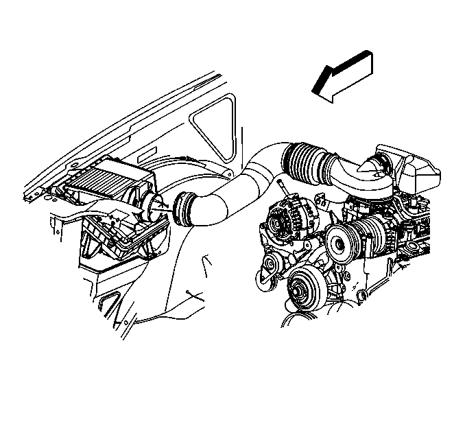
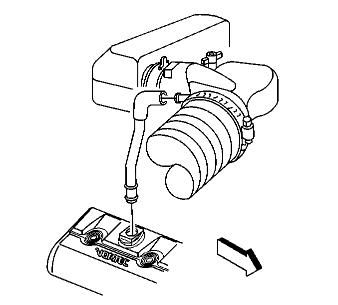
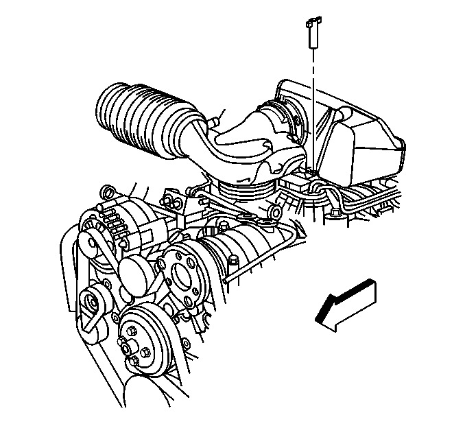
- Loosen the air cleaner outlet duct clamp at the mass airflow (MAF)/intake air temperature (IAT) sensor.
- Remove the positive crankcase ventilation (PCV) hose.
- Remove the air cleaner adapter nut.
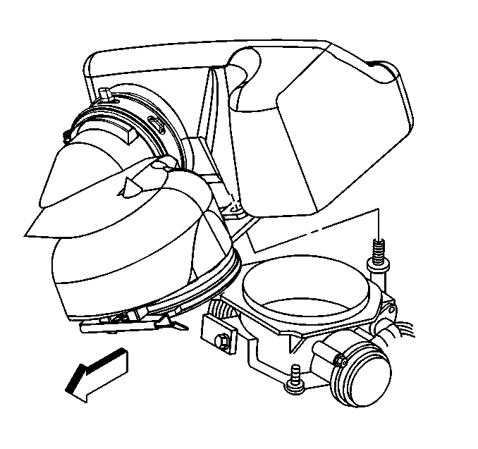
- In order to remove the air cleaner outlet duct, pivot the duct upward until the hinge clip releases from the lip on the throttle body.
- Remove the oil level indicator tube. Refer to Oil Level Indicator and Tube Replacement .
- Disconnect the spark plug wires from the spark plugs.
- Remove the spark plug wire retainer bolt.
- Reposition the wire retainer to the top of the engine.
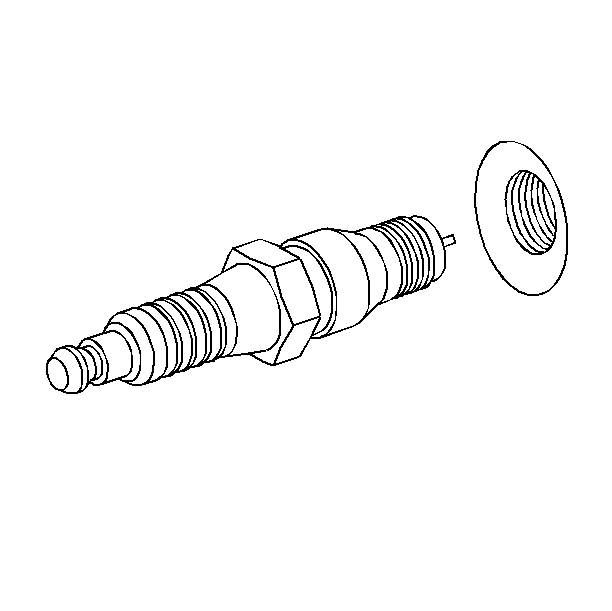
- Remove the spark plugs.
- Remove the exhaust manifold and spark plug heat shield bolts.
- Remove the exhaust manifold and spark plug heat shields.
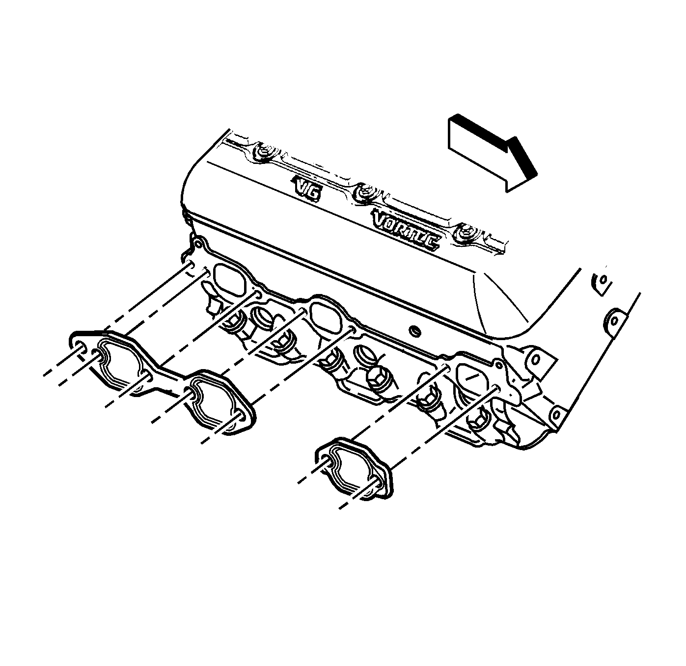
- Remove and discard the exhaust manifold gaskets.
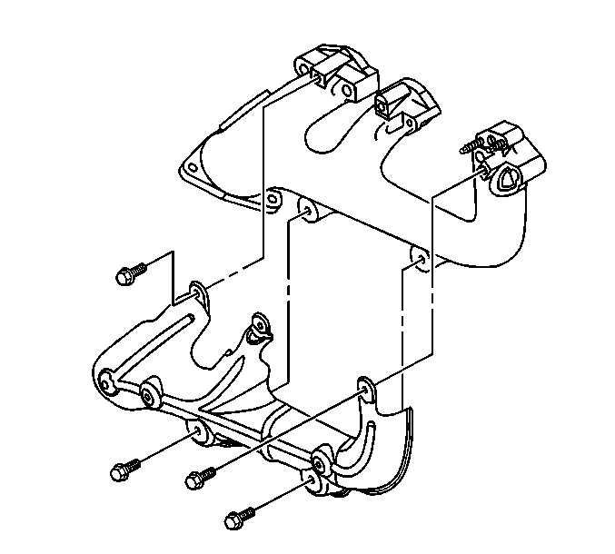
- Remove the exhaust manifold heat shield, if required.
- Clean all gasket mating surfaces.

Installation Procedure
- Install the exhaust manifold heat shield, if required.
- Install the exhaust manifold heat shield bolts.
- Install NEW exhaust manifold gaskets to the exhaust manifold.
- Ensure that the exhaust manifold bolts, and plug wire shields are held in place by the tabs on the exhaust manifold gaskets.
- Install the exhaust manifold and plug wire shields.
- If reusing the old fasteners, apply threadlock GM P/N 12345493, (Canadian P/N 10953488), or equivalent to the threads of the exhaust manifold bolts.
- Install the exhaust manifold bolts.
- Install the spark plugs.
- Position the spark plug wire retainer to the engine.
- Loosely install the spark plug wire retainer bolt.
- Connect the spark plug wires to the spark plugs.
- Install the oil level indicator tube. Refer to Oil Level Indicator and Tube Replacement .
- Tighten the spark plug wire retainer bolt.
- Align the hinge clip with the lip on the throttle body.
- Install the air cleaner adapter nut.
- Install the PCV hose.
- Tighten the air cleaner outlet duct clamp at the MAF/IAT sensor.
- Raise the vehicle.
- Install the right exhaust manifold pipe nuts.
- Lower the vehicle.

Notice: Use the correct fastener in the correct location. Replacement fasteners must be the correct part number for that application. Fasteners requiring replacement or fasteners requiring the use of thread locking compound or sealant are identified in the service procedure. Do not use paints, lubricants, or corrosion inhibitors on fasteners or fastener joint surfaces unless specified. These coatings affect fastener torque and joint clamping force and may damage the fastener. Use the correct tightening sequence and specifications when installing fasteners in order to avoid damage to parts and systems.
Tighten
Tighten the bolts to 9 N·m (80 lb in).
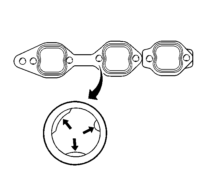
Important: To assist in installing the exhaust manifold and gasket to the engine, tabs on a NEW exhaust manifold gasket will hold the gasket and bolts in place.

Tighten
Tighten the bolts to 30 N·m (22 lb ft).

Tighten
Tighten the bolt to 12 N·m (106 lb in).

In order to install the air cleaner outlet duct, pivot the air cleaner outlet duct downward until the mounting stud is through the hole.


Tighten
Tighten the nuts to 50 N·m (37 lb ft).
Exhaust Manifold Replacement - Right Side 6.6L (LB7) Engine
Removal Procedure
- Raise the vehicle enough in order to work through the wheelhouse opening. Refer to Lifting and Jacking the Vehicle in General Information.
- Remove the wheelhouse panel. Refer to Wheelhouse Panel Replacement in Body Front End.
- Remove the front tire and wheel, if necessary. Refer to Tire and Wheel Removal and Installation in Tires and Wheels.
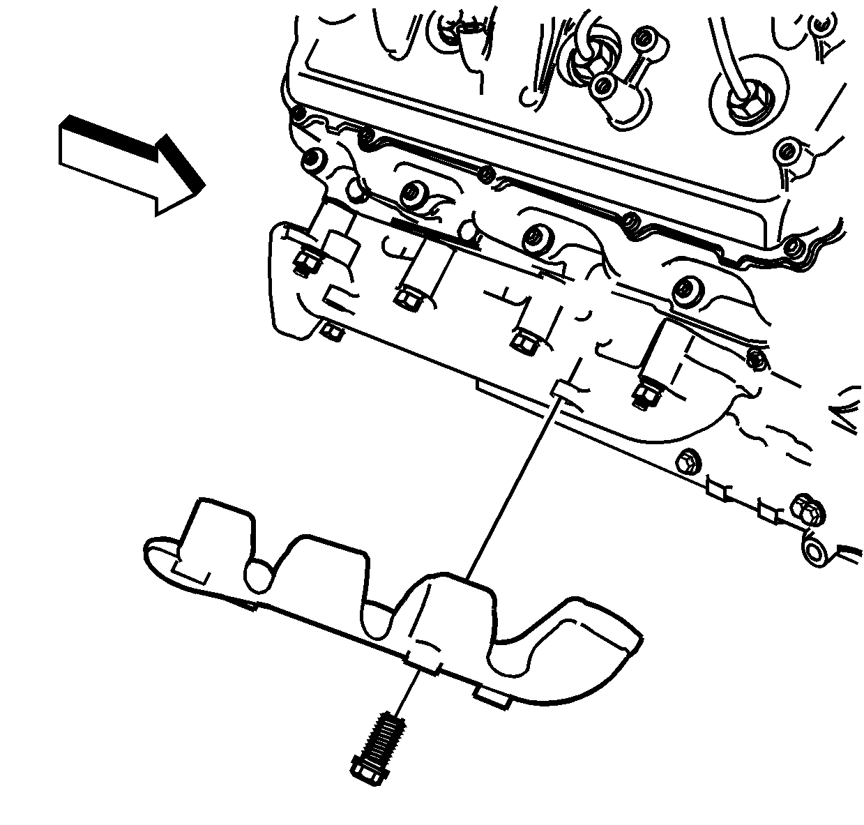
- Remove the exhaust manifold heat shield bolts.
- Remove the exhaust manifold heat shield.
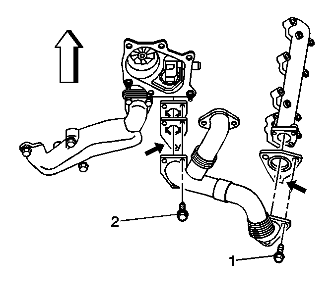
- Remove the right exhaust pipe to the exhaust manifold bolts (1).
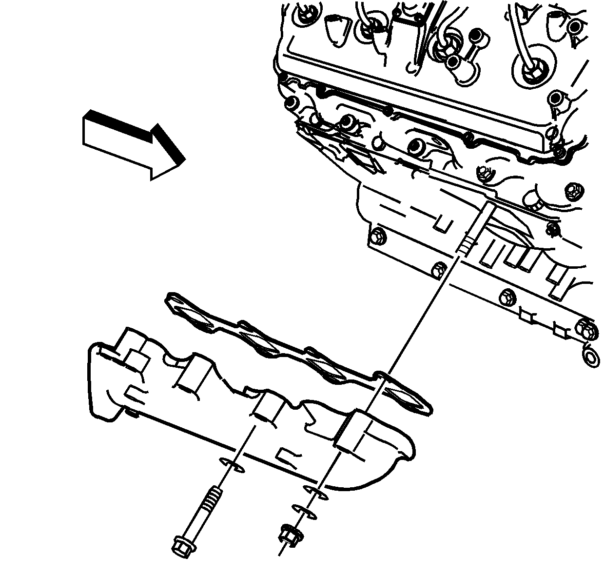
- Remove the bolts/nuts from the right exhaust manifold.
- Remove the exhaust manifold.
- Remove the bolt for the oil level indicator tube bracket in order to remove the exhaust manifold gasket.
- Remove and discard the exhaust manifold gasket.
- Clean and inspect the exhaust manifold. Refer to Exhaust Manifold Cleaning and Inspection in Engine Mechanical - 6.6L (LB7).
Installation Procedure
- Install the exhaust manifold gasket to the cylinder head.
- Install the bolt for the oil level indicator tube bracket.
- Install the exhaust manifold.
- Install the exhaust manifold bolts/nuts.
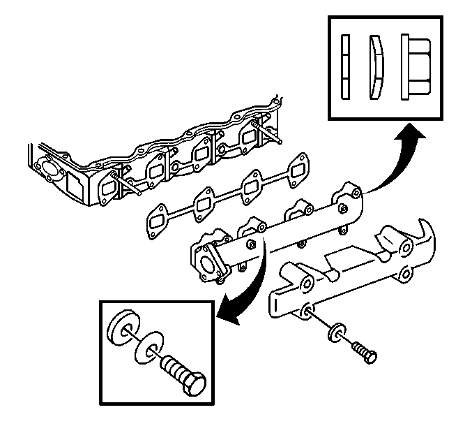
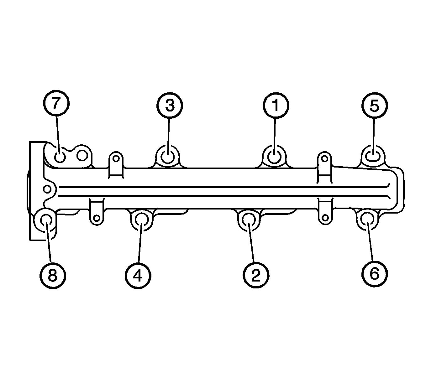
- Using the sequence shown, properly tighten the exhaust manifold bolts.
- Tighten the bolt/nuts a first pass to 34 N·m (25 lb ft).
- Tighten the bolts/nuts a final pass to 34 N·m (25 lb ft).
- Install the exhaust manifold heat shield.
- Install the exhaust manifold heat shield bolts.
- Install the exhaust pipe gasket. Align the tab on the gasket to face outward.
- Install the exhaust pipe bolts (1).
- Install the wheelhouse panel. Refer to Wheelhouse Panel Replacement in Body Front End.
- Install the front tire and wheel, if necessary. Refer to Tire and Wheel Removal and Installation in Tires and Wheels.
- Lower the vehicle.
Notice: Refer to Fastener Notice in the Preface section.
Tighten
Tighten the bolt to 21 N·m (15 lb ft).
Tighten

Tighten
Tighten the bolts to 8 N·m (71 lb in).

Tighten
Tighten the bolts to 53 N·m (39 lb ft).
Exhaust Manifold Replacement - Right Side 8.1L Engine
Removal Procedure
- Remove the wheelhouse panel. Refer to Wheelhouse Panel Replacement in Body Front End.
- Remove the oil level indicator. Refer to Oil Level Indicator and Tube Replacement in Engine Mechanical - 8.1L.
- Remove the spark plug wires from the spark plugs and ignition coils.
- Remove the spark plugs. Refer to Spark Plug Replacement in Engine Controls - 8.1L.
- Raise and suitably support the vehicle. Refer to Lifting and Jacking the Vehicle in General Information.
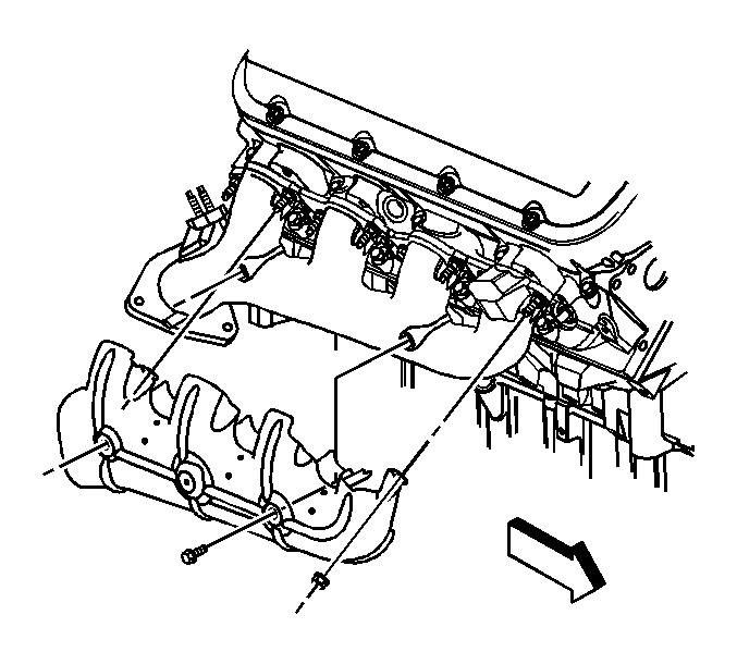
- Remove the exhaust manifold heat shield bolts and nuts.
- Remove the exhaust manifold heat shield.
- Lower the vehicle.
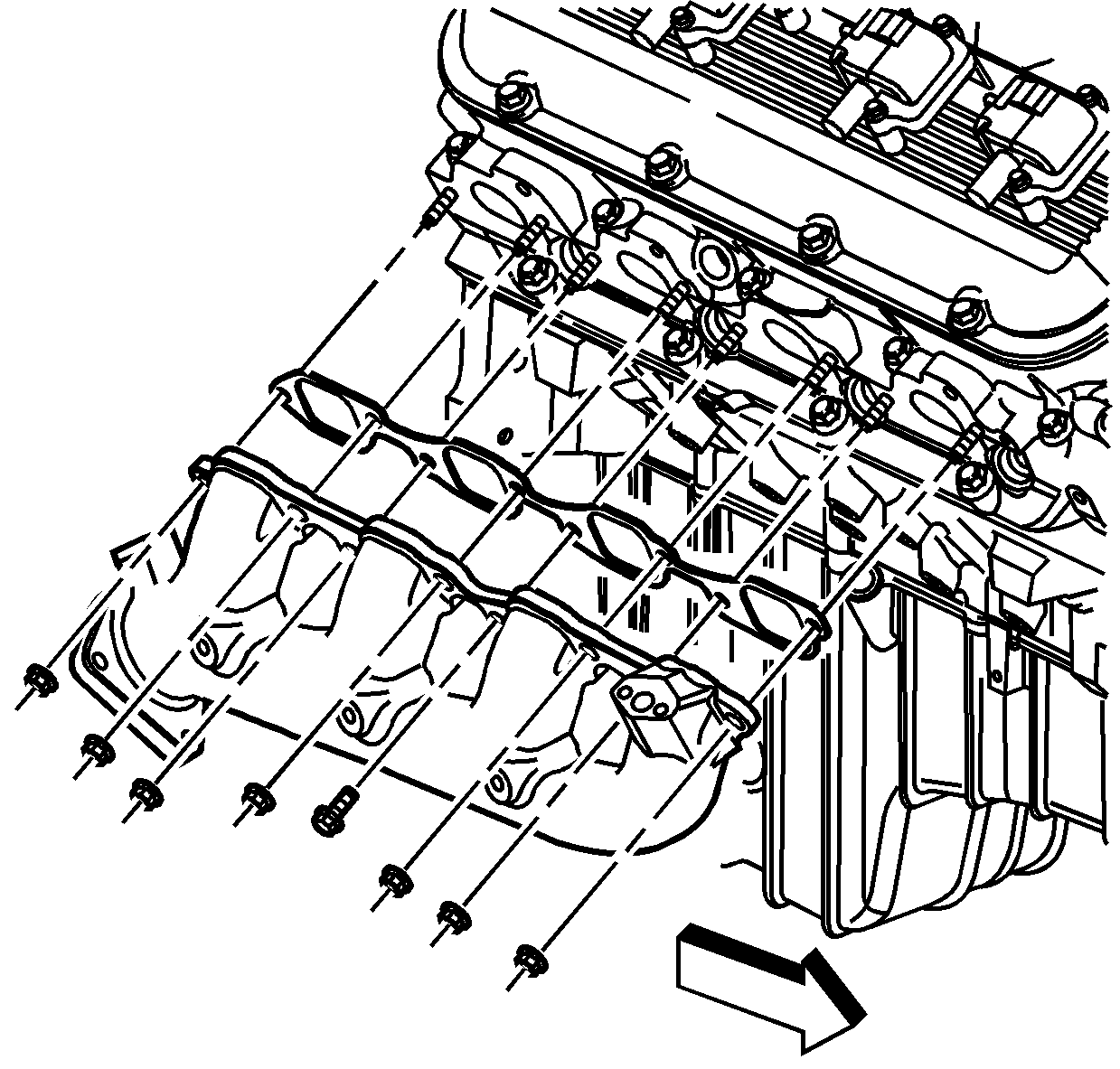
- Remove the exhaust manifold bolt and nuts.
- Remove the exhaust manifold.
- Remove and discard the exhaust manifold gasket.
- Clean and inspect the exhaust manifold. Refer to Exhaust Manifold Cleaning and Inspection .
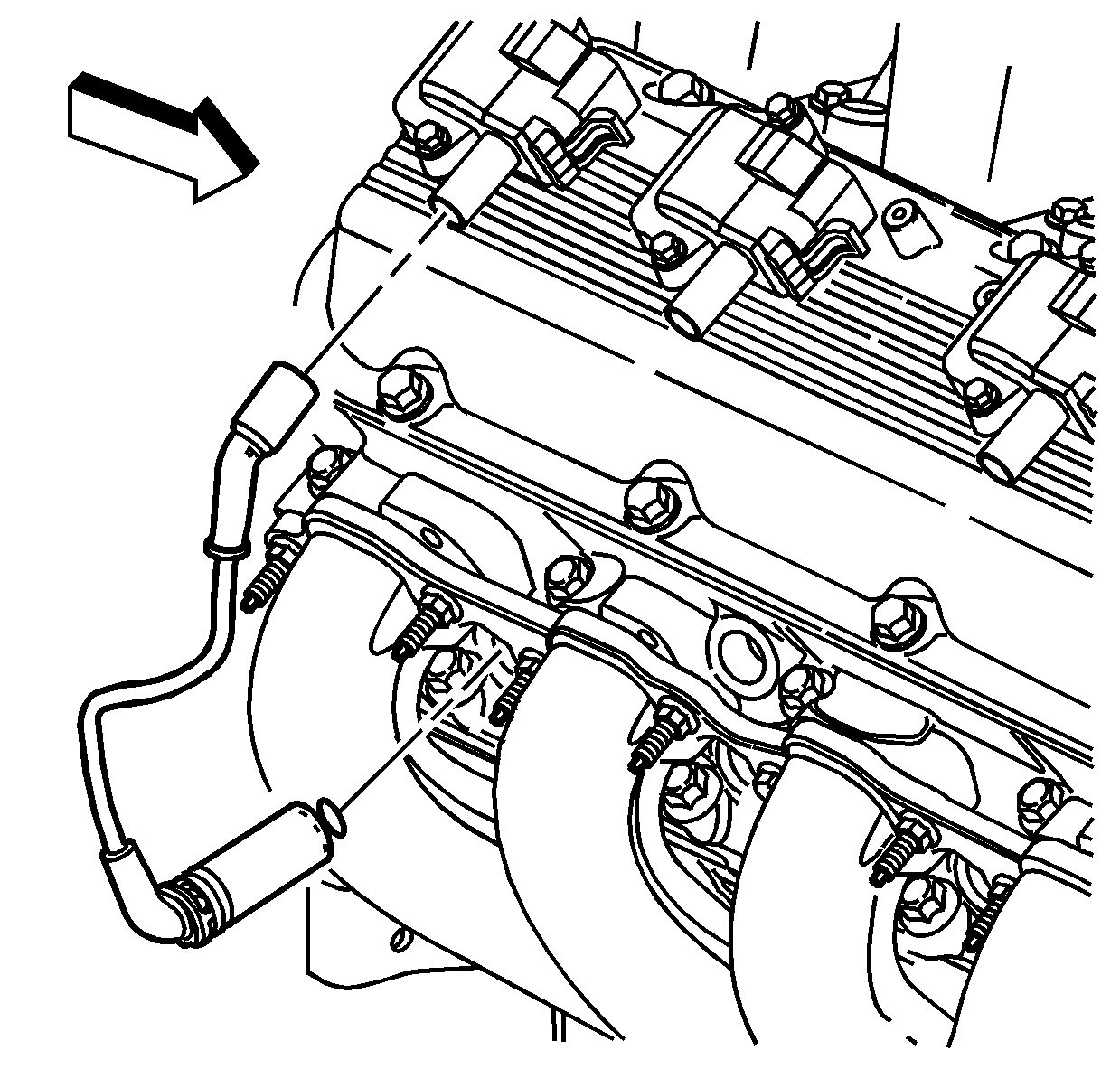
Important: Twist the spark plug boot one-half turn in order to release the boot. Pull on the spark plug boot only. Do not pull on the spark plug or the wire could be damaged.
Installation Procedure
- Install the a NEW exhaust manifold gasket.
- Install the exhaust manifold.
- Install the exhaust manifold bolt and nuts.
- Raise and suitably support the vehicle with safety stands.
- Install the exhaust manifold heat shield.
- Install the exhaust manifold heat shield bolts and nuts.
- Lower the vehicle.
- Install the spark plugs. Refer to Spark Plug Replacement in Engine Controls - 8.1L.
- Install the spark plug wires to the spark plugs and ignition coils.
- Install the oil level indicator. Refer to Oil Level Indicator and Tube Replacement in Engine Mechanical - 8.1L.
- Install the wheelhouse panel. Refer to Wheelhouse Panel Replacement in Body Front End.

Notice: Use the correct fastener in the correct location. Replacement fasteners must be the correct part number for that application. Fasteners requiring replacement or fasteners requiring the use of thread locking compound or sealant are identified in the service procedure. Do not use paints, lubricants, or corrosion inhibitors on fasteners or fastener joint surfaces unless specified. These coatings affect fastener torque and joint clamping force and may damage the fastener. Use the correct tightening sequence and specifications when installing fasteners in order to avoid damage to parts and systems.
Tighten
| • | Tighten the bolt to 35 N·m (26 lb ft). |
| • | Tighten the nuts to 16 N·m (12 lb ft). |

Tighten
Tighten the bolts/nuts to 25 N·m (18 lb ft).

Important: Fully install the spark plug wires by pushing on the exposed end of the spark plug boot. Do not push the spark plug wire on to the spark plug by using the metal heat shield.
Exhaust Manifold Replacement - Right Side 6.6L (LLY) Engine
Removal Procedure
- Raise the vehicle enough in order to work through the wheelhouse opening. Refer to Lifting and Jacking the Vehicle in General Information.
- Remove the wheelhouse panel. Refer to Wheelhouse Panel Replacement in Body Front End.
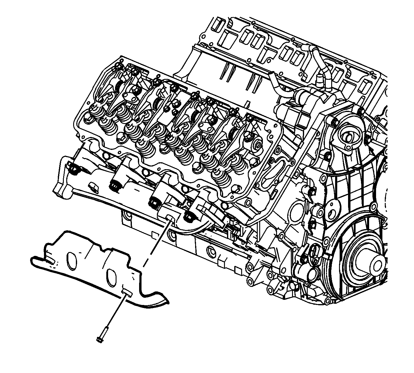
- Remove the exhaust manifold heat shield bolts.
- Remove the exhaust manifold heat shield.
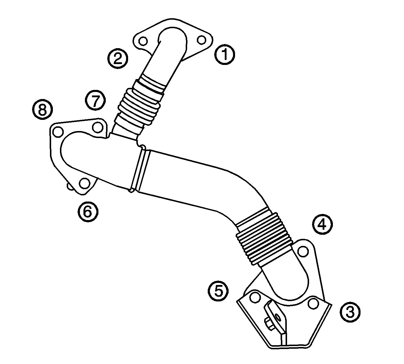
- Remove the right exhaust pipe to the exhaust manifold bolts (3, 4, and 5).
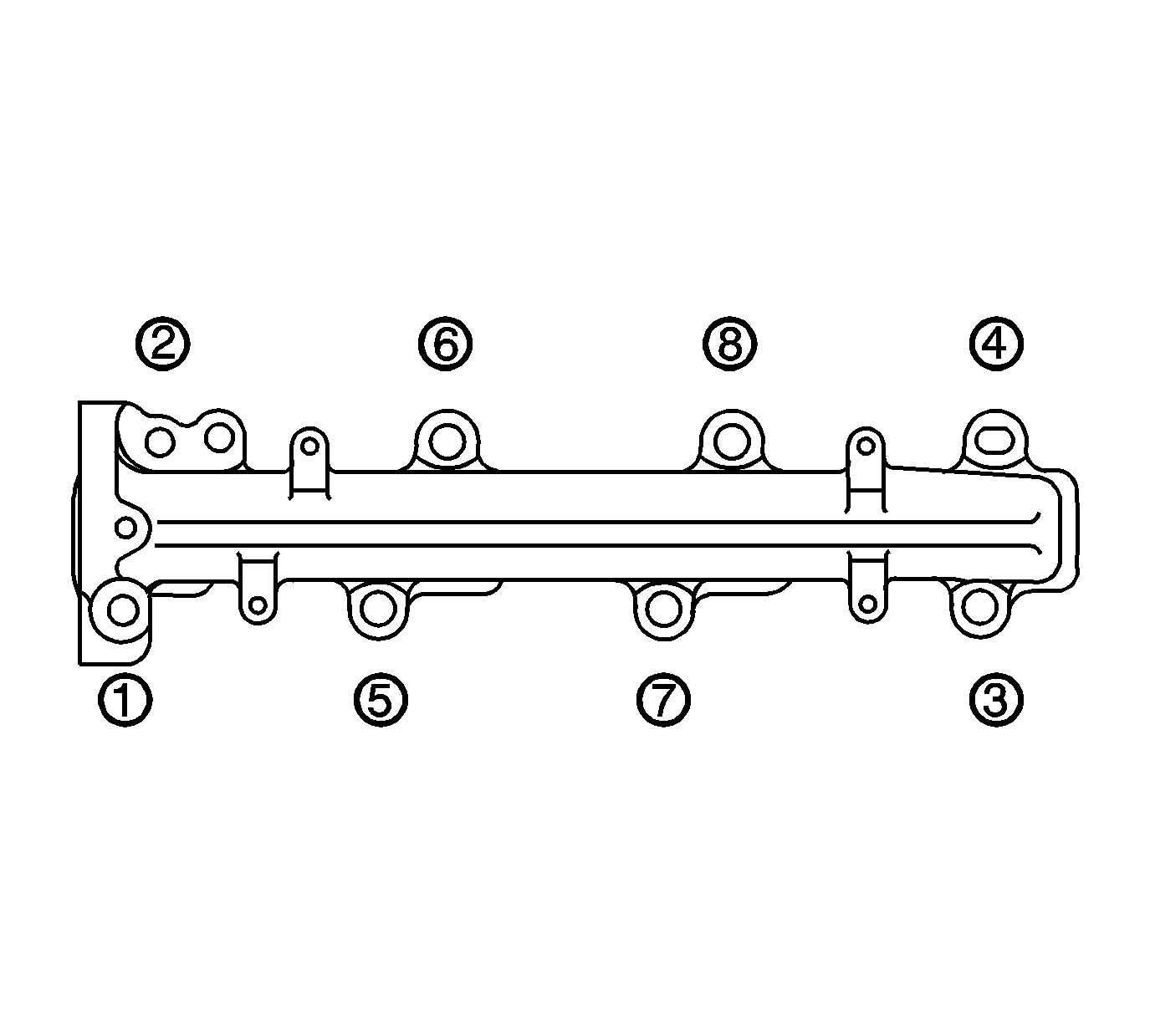
- Remove the exhaust manifold bolts and nuts in the proper sequence.
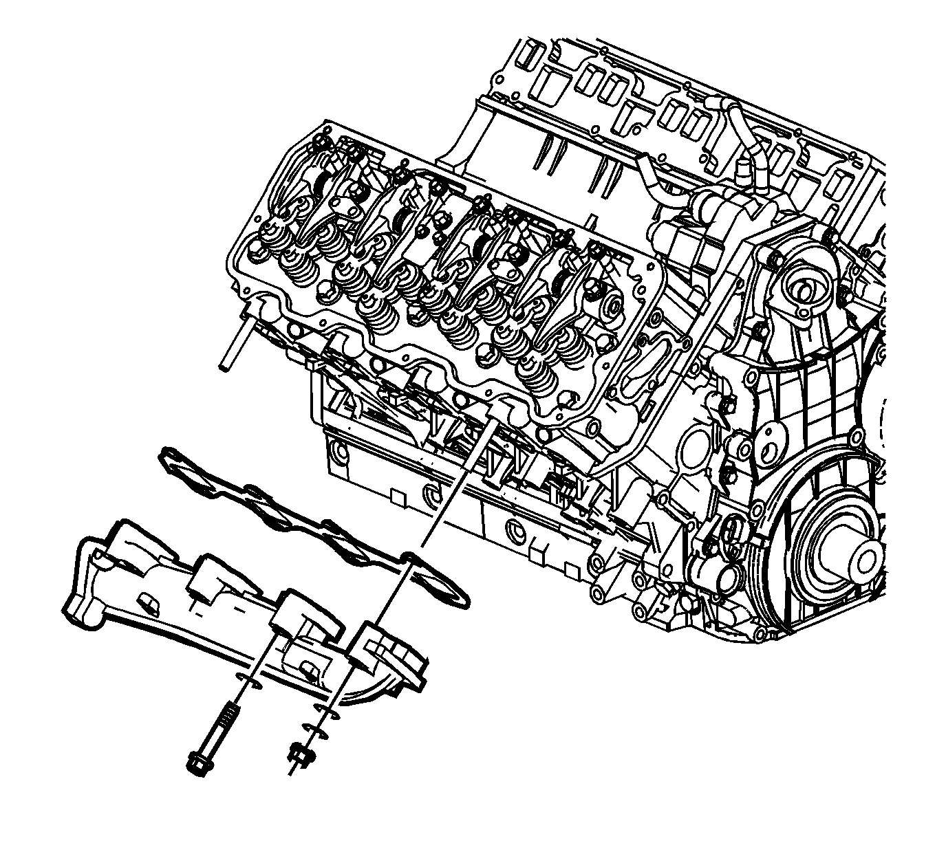
- Remove the exhaust manifold.
- Remove the bolt for the oil level indicator tube bracket in order to remove the exhaust manifold gasket.
- Remove and discard the exhaust manifold gasket.
- Clean and inspect the exhaust manifold. Refer to Exhaust Manifold Cleaning and Inspection in Engine Mechanical - 6.6L (LLY).
Installation Procedure
- Install the exhaust manifold gasket to the cylinder head.
- Install the bolt for the oil level indicator tube bracket.
- Install the exhaust manifold.
- Install the exhaust manifold bolts/nuts.
- Using the sequence shown, properly tighten the exhaust manifold bolts.
- Install the exhaust manifold heat shield.
- Install the exhaust manifold heat shield bolts.
- Install the exhaust pipe gasket. Align the tab on the gasket to face outward.
- Install the exhaust pipe bolts (3, 4, and 5).
- Install the wheelhouse panel. Refer to Wheelhouse Panel Replacement in Body Front End.
- Lower the vehicle.
Notice: Refer to Fastener Notice in the Preface section.

Tighten
Tighten the bolt to 21 N·m (15 lb ft).

Tighten
Tighten the bolt/nuts to 38 N·m (28 lb ft).

Tighten
Tighten the bolts to 8 N·m (71 lb in).
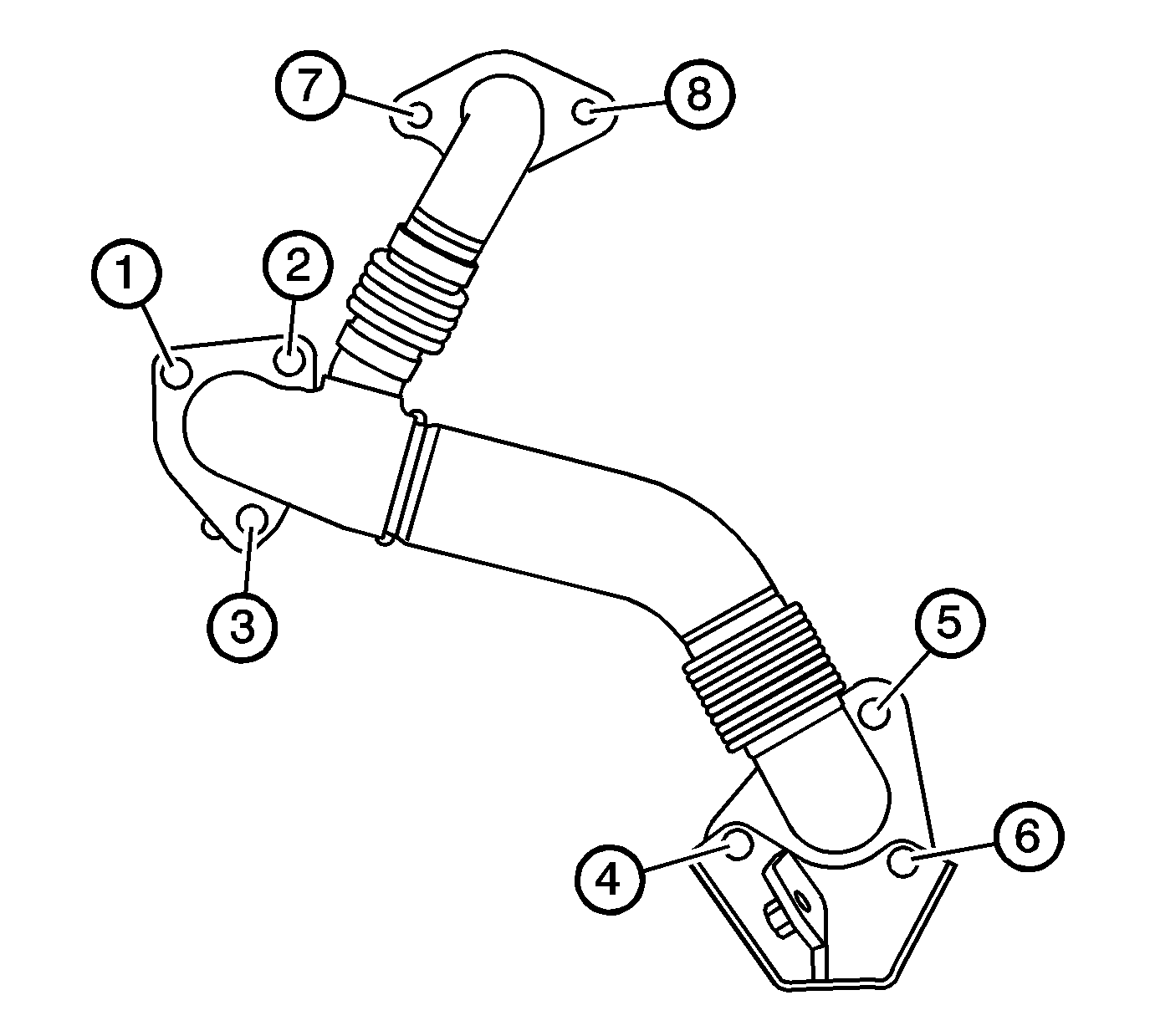
Tighten
Tighten the bolts to 53 N·m (39 lb ft).
