Fuel Tank Replacement Pickup - 5.3L (L59) Engine
Removal Procedure
Important: Clean the fuel and evaporative emission (EVAP) connections and surrounding areas
prior to disconnecting the lines in order to avoid possible system contamination.
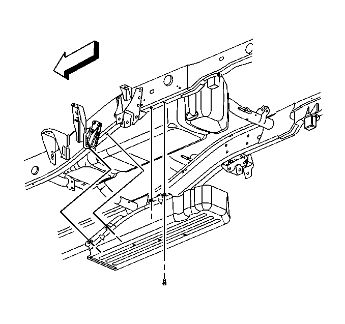
- Relieve the fuel system pressure. Refer
to
Fuel Pressure Relief
.
- Drain the fuel tank. Refer to
Fuel Tank Draining
.
- Remove the fuel tank fill pipe. Refer to
Filler Tube Replacement
.
- Remove the evaporative emission (EVAP) canister. Refer to
Evaporative Emission Canister Replacement
.
- If equipped, remove the fuel tank shield bolts.
- If equipped, remove the fuel tank shield.
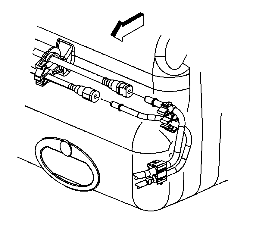
- Disconnect the fuel feed and return line
quick connect fittings. Refer to
Plastic Collar Quick Connect Fitting Service
.
- Cap the fuel lines in order to avoid possible system contamination.
- Place a suitable adjustable jack under the fuel tank.
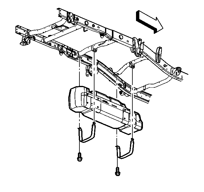
- Remove the fuel tank strap bolts.
- Remove the fuel tank straps.
- Lower the fuel tank until the electrical connections are accessible.
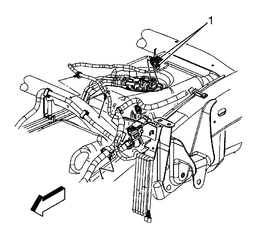
- Remove the fuel sending unit connector position
assurance (CPA) retainer.
- Disconnect the fuel sending unit and fuel pressure sensor electrical connectors
(1).
- Completely lower the fuel tank.
- With the aid of an assistant, place the fuel tank in a suitable work area.
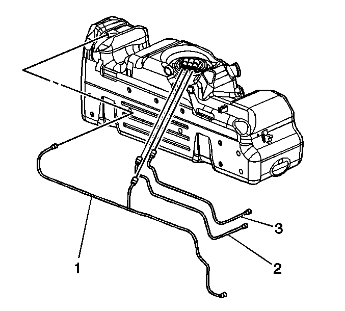
- If necessary, disconnect and remove the
fuel feed (3) and return (2) pipes from the sending unit and retaining clips.
- If necessary, disconnect and remove the EVAP pipe (1) from the sending
unit, roll over valve (3), and retaining clip.
- If necessary, remove the sending unit. Refer to
Fuel Sender Assembly Replacement
.
Installation Procedure

- If necessary, install the sending unit.
Refer to
Fuel Sender Assembly Replacement
.
- If necessary, install and connect the EVAP pipe (1) to the sending unit,
roll over valve (3), and retaining clip.
- If necessary, install and connect the fuel feed (3) and return (2) pipes
to the sending unit and retaining clips.

- With the aid of an assistant, place the
fuel tank on the jack.
- Raise the fuel tank until the electrical connections can be made.
- Connect the fuel sending unit and fuel pressure sensor electrical connectors
(1).
- Install the fuel sending unit CPA retainer.

- Completely raise the fuel tank.
Notice: Refer to Fastener Notice in the Preface section.
- Install the fuel tank straps.
- Install the fuel tank strap bolts.
Tighten
Tighten the bolts to 40 N·m (30 lb ft).
- Remove the adjustable jack from under the fuel tank.

- Remove the caps from the fuel lines.
- Connect the fuel feed and return line quick connect fittings. Refer to
Plastic Collar Quick Connect Fitting Service
.
- Install the fuel feed and return lines to the clip on the fuel tank.

- If equipped, install the fuel tank shield.
- If equipped, install the fuel tank shield bolts.
Tighten
Tighten the bolts to 18 N·m (13 lb ft).
- Install the EVAP canister. Refer to
Evaporative Emission Canister Replacement
.
- Install the fuel tank fill pipe. Refer to
Filler Tube Replacement
.
- Refill the fuel tank.
- Install the fuel cap.
- Connect the negative battery cable. Refer to
Battery Negative Cable Disconnection and Connection
in Engine Electrical.
- Perform the following procedure in order to inspect for leaks:
| 22.1. | Turn the ignition ON, with the engine OFF, for 2 seconds. |
| 22.2. | Turn the ignition OFF for 10 seconds. |
| 22.3. | Turn the ignition ON, with the engine OFF. |
| 22.4. | Inspect for fuel leaks. |
Fuel Tank Replacement Pickup
Removal Procedure
Important: Clean the fuel and evaporative emission (EVAP) connections and surrounding areas prior to disconnecting the lines in order to avoid possible system contamination.

- Relieve the fuel system pressure. Refer to
Fuel Pressure Relief.
- Drain the fuel tank. Refer to
Fuel Tank Draining.
- Remove the fuel tank fill pipe. Refer to
Filler Tube Replacement.
- Remove the EVAP canister vent solenoid. Refer to
Evaporative Emission Canister Vent Solenoid Valve Replacement.
- Remove the fuel tank shield bolts, if equipped.
- Remove the fuel tank shield, if equipped.
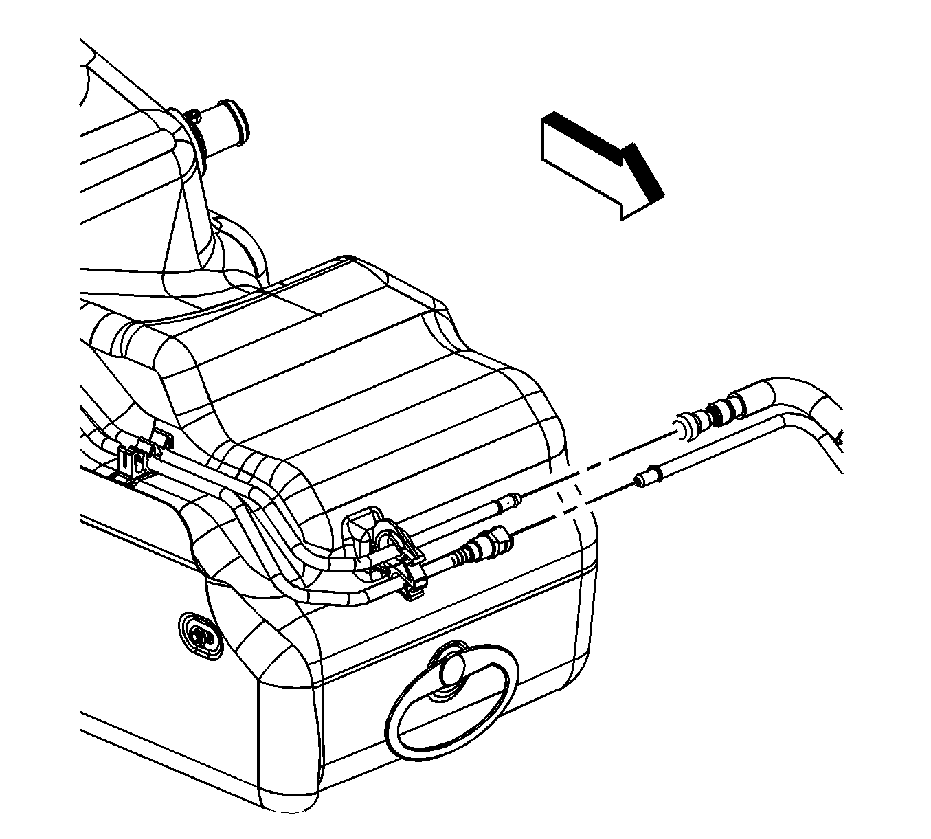
- Disconnect the fuel feed and EVAP lines. Refer to
Plastic Collar Quick Connect Fitting Service.
- Cap the fuel and EVAP lines in order to prevent possible system contamination.
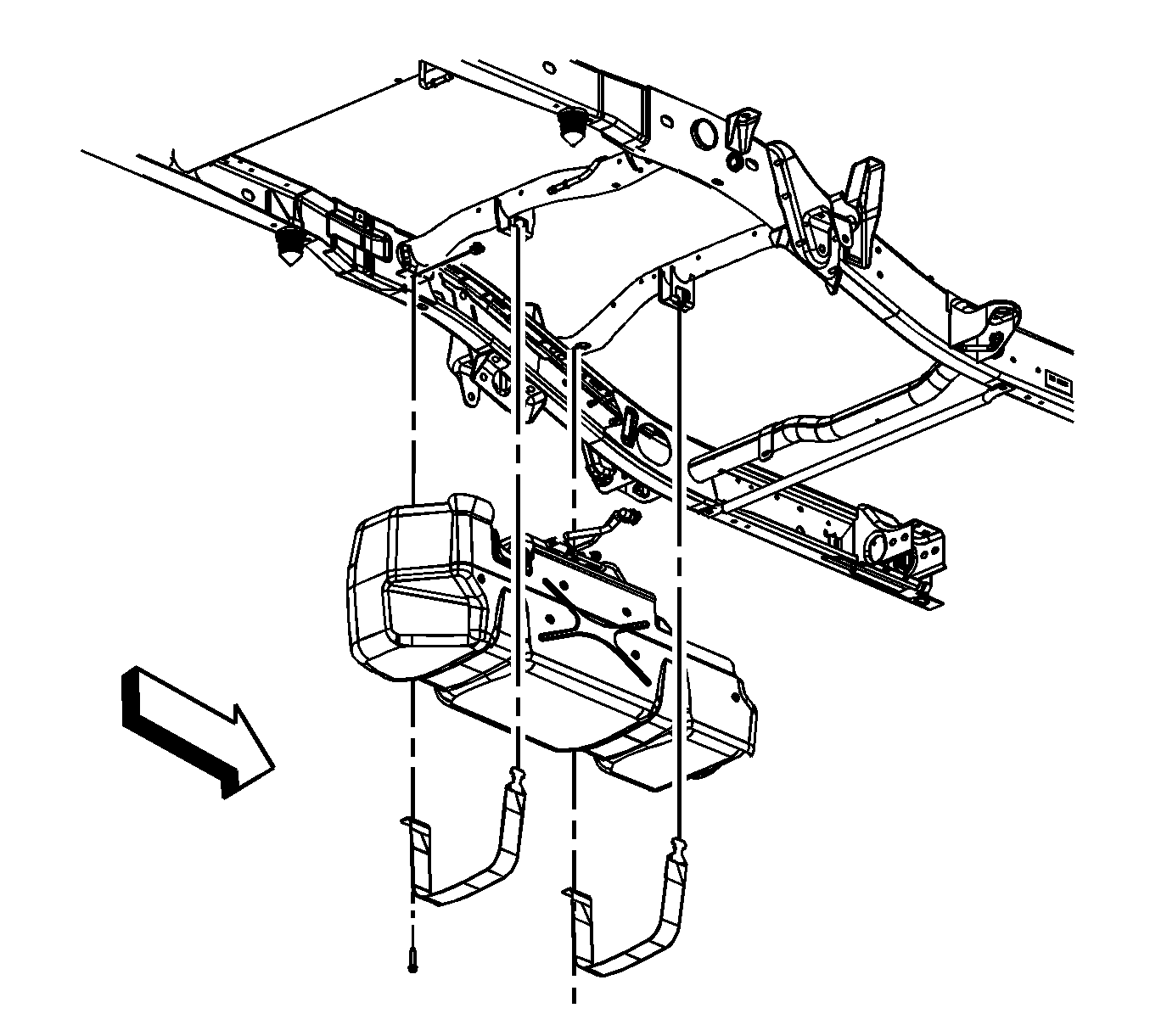
- Place a suitable adjustable jack under the fuel tank.
- Remove the fuel tank strap bolts.
- Remove the fuel tank straps.
- Lower the fuel tank half way.
When lowering the tank, ensure that the fill neck on the tank does not get hung up on the harness.
- Disconnect the electrical harness clip at the frame crossmember.
- Lower the fuel tank until the electrical connections are accessible.
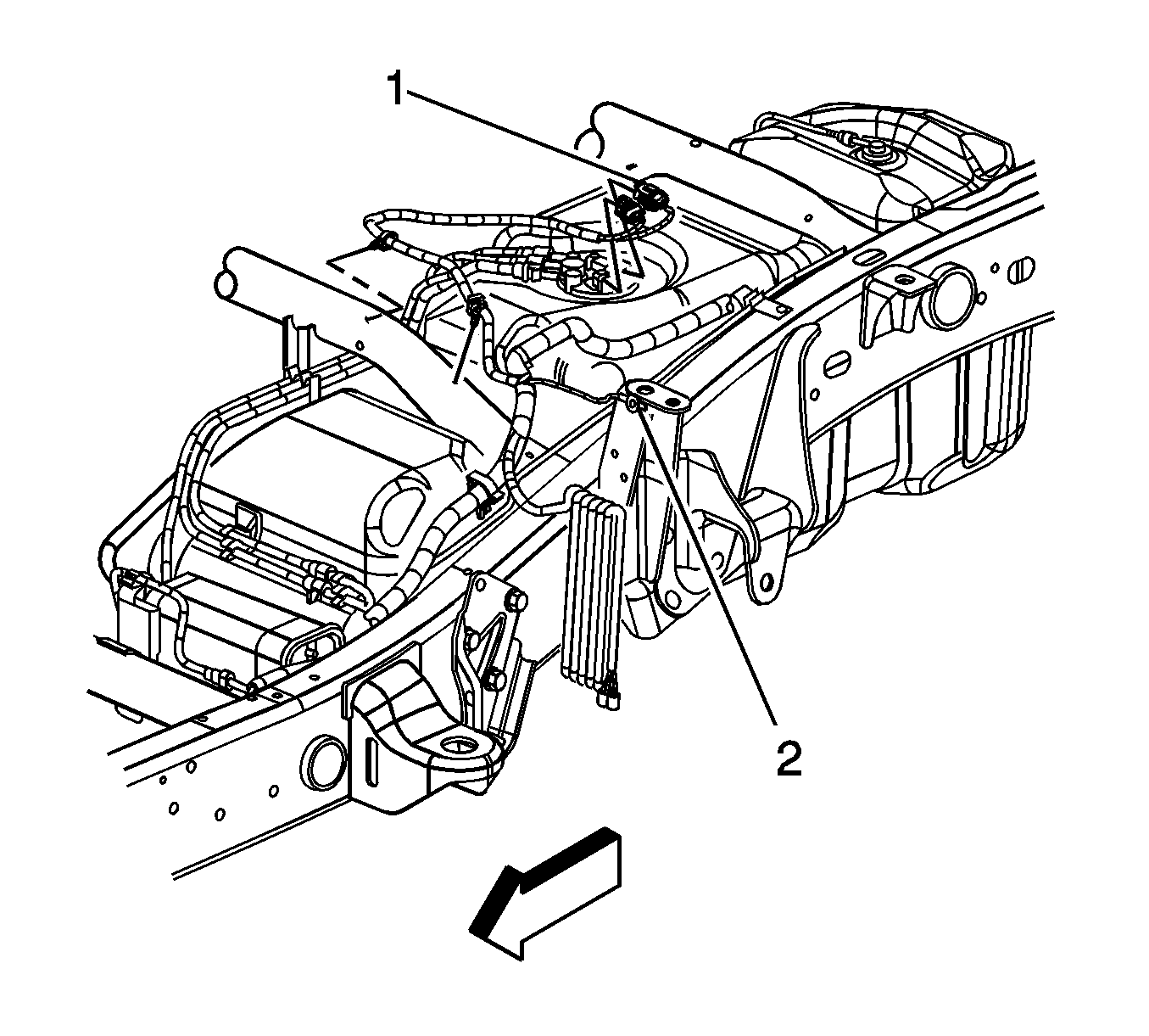
- Disconnect the fuel pressure sensor electrical connector.
- Disconnect the fuel sending unit electrical connector, perform the following:
| 16.1. | Disengage the gray retainer. |
| 16.2. | Push down the black clip. |
| 16.3. | Disconnect the connector. |
- Completely lower the fuel tank.
- With the aid of an assistant, place the fuel tank in a suitable work area.
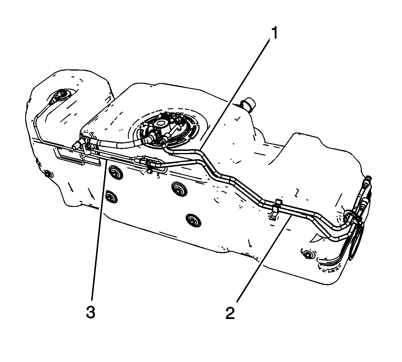
- If necessary, disconnect and remove the fuel feed line (1) from the sending unit and retaining clips.
- If necessary, disconnect and remove the EVAP purge line (2) from the retaining clips.
- If necessary, disconnect and remove the EVAP fuel level vent valve (FLVV) line from the FLVV, sending unit, and retaining clips.
- If necessary, remove the sending unit. Refer to
Fuel Sender Assembly Replacement.
Installation Procedure

- If necessary, install the sending unit. Refer to
Fuel Sender Assembly Replacement.
- If necessary, install and connect the EVAP FLVV line to the FLVV, sending unit, and retaining clips.
- If necessary, install and connect the EVAP purge line (2) to the retaining clips.
- If necessary, install and connect the fuel feed line (1) to the sending unit and retaining clips.

- With the aid of an assistant, place the fuel tank onto the adjustable jack.
- Raise the fuel tank until the electrical connections can be made.
- Connect the fuel sending unit and pressure sensor electrical connectors.
- Completely raise the fuel tank.
When raising the tank, ensure that the fill neck on the tank goes over the harness.
Notice: Refer to Fastener Notice in the Preface section.

- Install the fuel tank straps.
- Install the fuel tank strap bolts.
Tighten
Tighten the bolts to 40 N·m (30 lb ft).
- Remove the adjustable jack from under the fuel tank.

- Remove the caps from the fuel and EVAP lines.
- Connect the fuel feed and EVAP lines. Refer to
Plastic Collar Quick Connect Fitting Service.

- If necessary, install the fuel tank shield.
- If necessary, install the fuel tank shield bolts.
Tighten
Tighten the bolts to 18 N·m (13 lb ft).
- Install the EVAP canister vent solenoid. Refer to
Evaporative Emission Canister Vent Solenoid Valve Replacement.
- Install the fuel tank fill pipe. Refer to
Filler Tube Replacement.
- Refill the fuel tank.
- Install the fuel cap.
- Connect the negative battery cable. Refer to
Battery Negative Cable Disconnection and Connection.
- Perform the following procedure in order to inspect for leaks:
| 21.1. | Turn the ignition ON, with the engine OFF, for 2 seconds. |
| 21.2. | Turn the ignition OFF for 10 seconds. |
| 21.3. | Turn the ignition ON, with the engine OFF. |
| 21.4. | Inspect for fuel leaks. |
Fuel Tank Replacement Cab/Chassis - Front
Removal Procedure
Important: Clean the fuel and evaporative emission (EVAP) connections and surrounding area prior to disconnecting the lines in order to avoid possible system contamination.
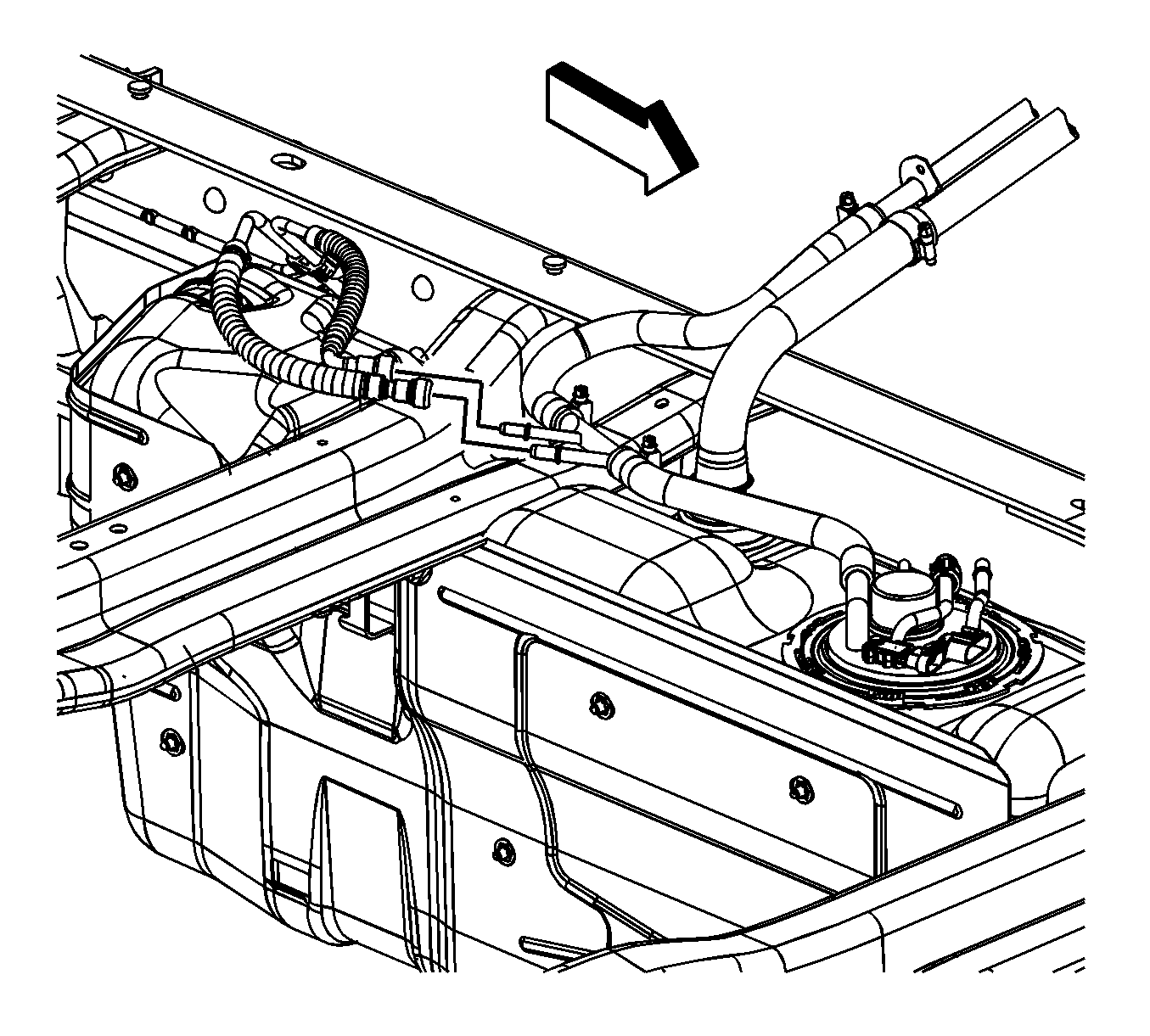
- Relieve the fuel system pressure. Refer to
Fuel Pressure Relief.
- If equipped with a rear auxiliary tank, disconnect the fuel feed and EVAP quick connect fittings. Refer to
Metal Collar Quick Connect Fitting Service.
- Cap the fuel feed and EVAP pipes in order to prevent possible system contamination.
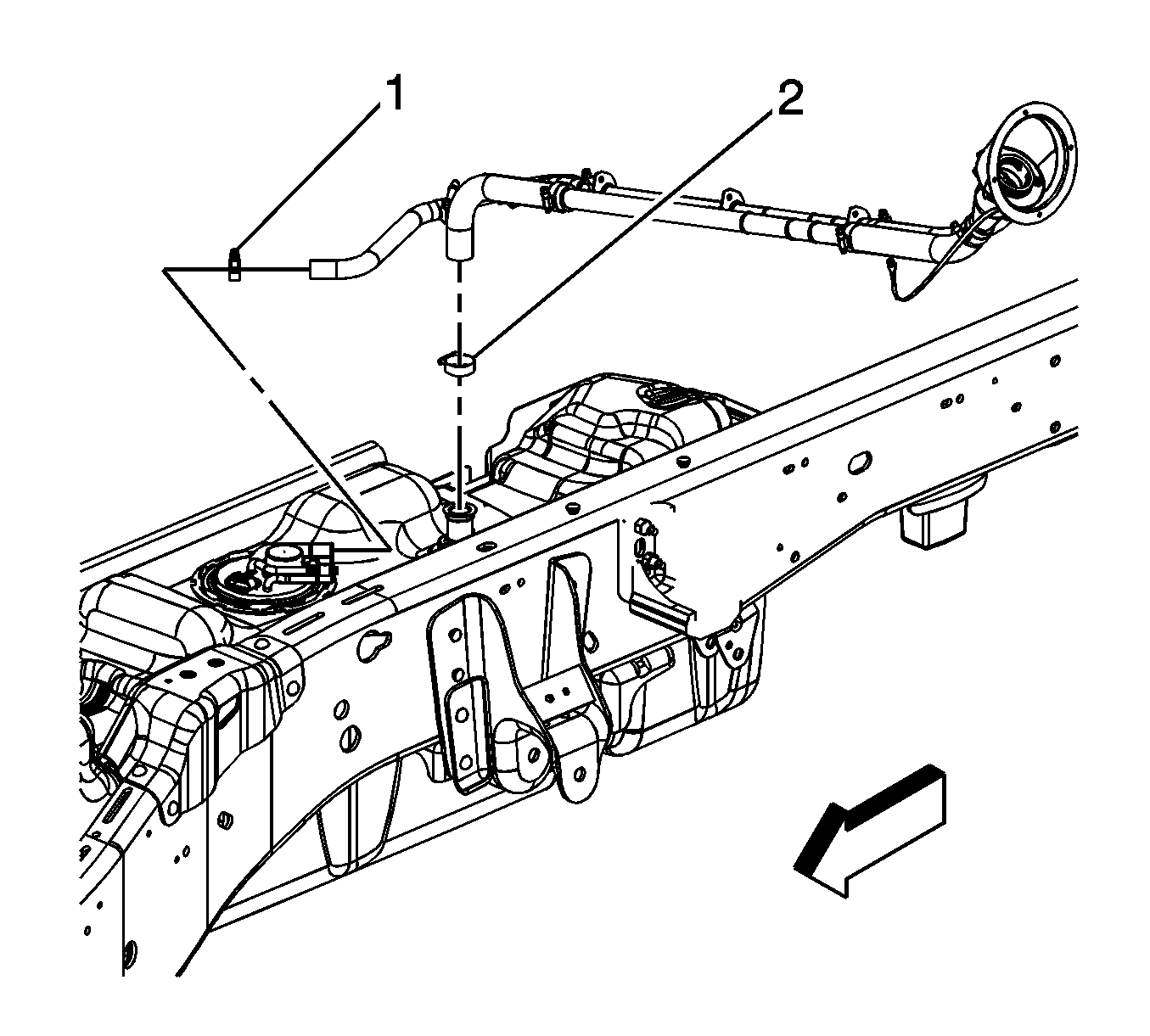
- Loosen the fuel fill pipe clamp (2) at the tank.
- Loosen the vent pipe clamp (1) at the tank.
- Remove the fuel fill pipe and vent pipe from the tank.
- Drain the fuel tank. Refer to
Fuel Tank Draining.
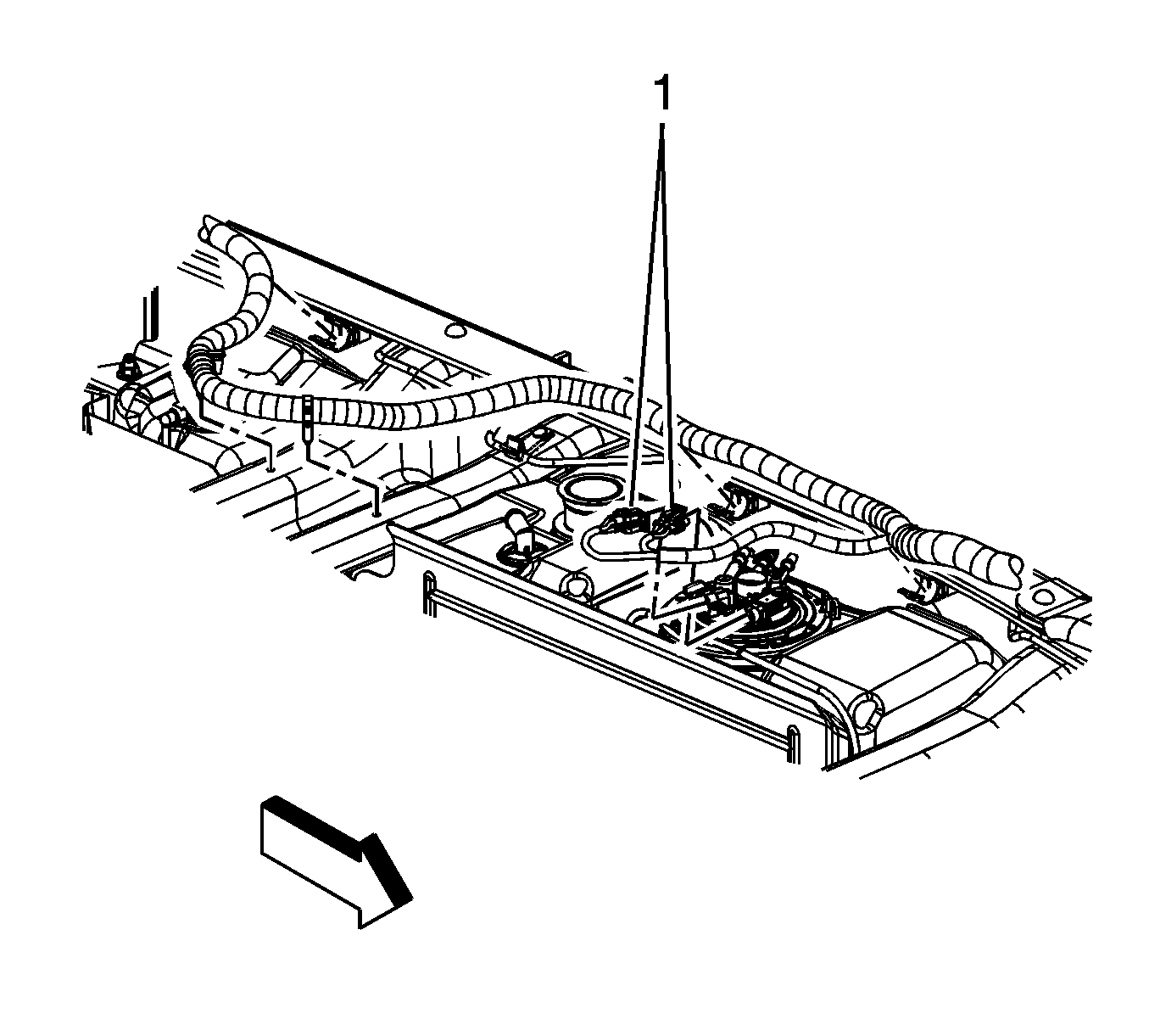
- Disconnect the fuel pressure sensor electrical connector (1).
- Disconnect the fuel sending unit electrical connector (1), perform the following:
| 9.1. | Disengage the gray retainer. |
| 9.2. | Push down the black clip. |
| 9.3. | Disconnect the connector. |
- Remove the canister vent solenoid (CVS) line from the fuel tank clips.
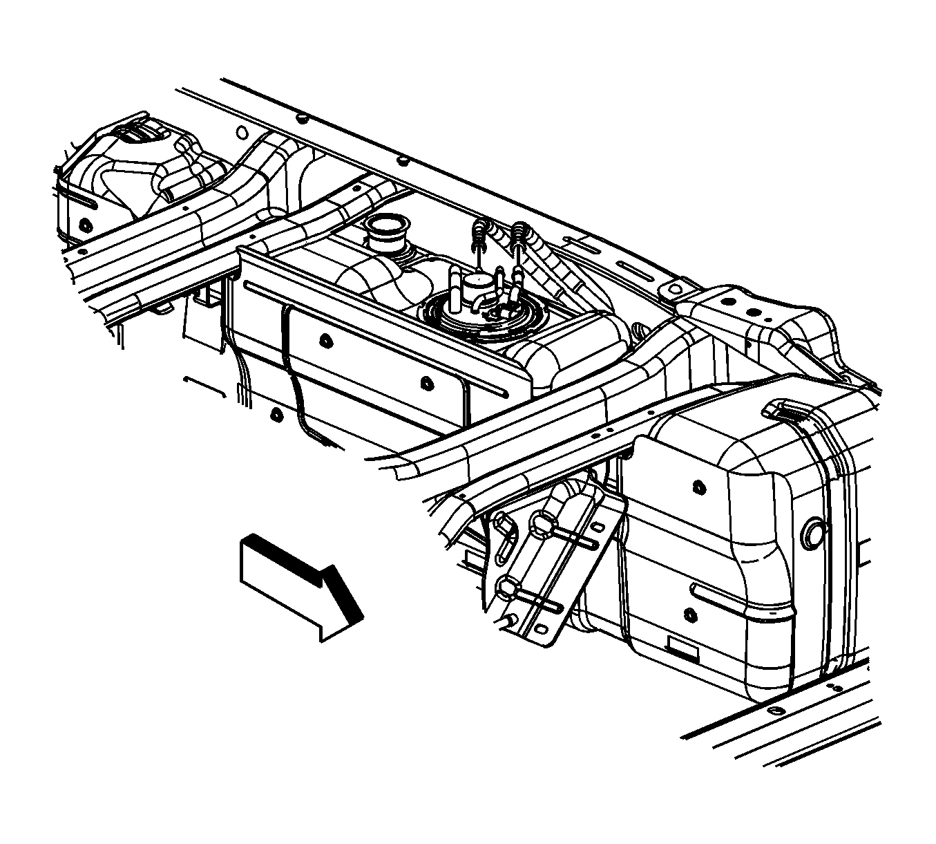
- Disconnect the fuel feed and EVAP quick connect fittings from the sending unit. Refer to
Metal Collar Quick Connect Fitting Service.
- Raise and suitably support the vehicle. Refer to
Lifting and Jacking the Vehicle.
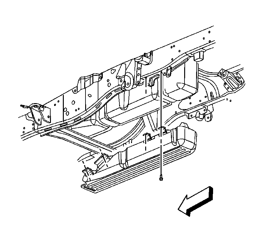
- Remove the fuel tank shield bolts.
- Remove the fuel tank shield.
- Place a suitable adjustable jack under the fuel tank.
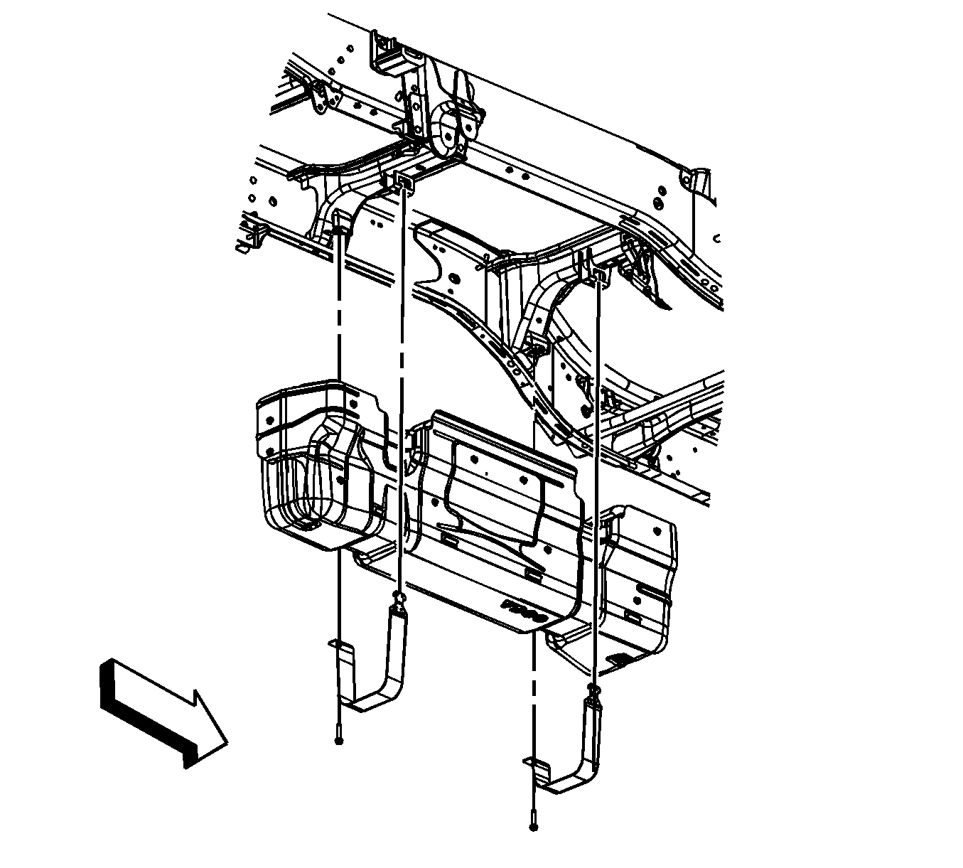
- Remove the fuel tank strap bolts.
- Remove the fuel tank straps.
- Lower the fuel tank.
- With the aid of an assistant, place the fuel tank in a suitable work area.
- Cap the fuel and EVAP pipes in order to prevent possible system contamination.
- If necessary, remove the sending unit. Refer to
Fuel Sender Assembly Replacement.
Installation Procedure

- If necessary, install the sending unit. Refer to
Fuel Sender Assembly Replacement.
- Remove the caps from the fuel and EVAP pipes.
- With the aid of an assistant, place the fuel tank on the jack.
- Raise the fuel tank.
Notice: Refer to Fastener Notice in the Preface section.
- Install the fuel tank straps.
- Install the fuel tank strap bolts.
Tighten
Tighten the bolts to 40 N·m (30 lb ft).

- Remove the jack from under the fuel tank.
- Install the fuel tank shield.
- Install the fuel tank shield bolts.
Tighten
Tighten the bolts to 18 N·m (13 lb ft).
- Lower the vehicle.

- Connect the fuel feed and EVAP quick connect fittings to the sending unit. Refer to
Metal Collar Quick Connect Fitting Service.

- Connect the fuel sending unit and fuel pressure sensor electrical connectors (1).
- Install the CVS line to the fuel tank clips.

- Install the fuel fill pipe and vent pipe to the tank.
- Tighten the vent pipe clamp (1) at the tank.
- Tighten the fuel fill pipe clamp (2) at the tank.
Tighten
Tighten the clamps to 2.5 N·m (22 lb in).

- Remove the caps from the fuel feed and EVAP pipes.
- If equipped with a rear auxiliary tank, connect the fuel feed and EVAP quick connect fittings. Refer to
Metal Collar Quick Connect Fitting Service.
- Refill the fuel tank.
- Install the fuel fill cap.
- Connect the negative battery cable. Refer to
Battery Negative Cable Disconnection and Connection.
- Perform the following steps in order to inspect for leaks.
| 22.1. | Turn the ignition ON, with the engine OFF, for 2 seconds. |
| 22.2. | Turn the ignition OFF for 10 seconds. |
| 22.3. | Turn the ignition ON, with the engine OFF. |
| 22.4. | Inspect for fuel leaks. |
Fuel Tank Replacement Cab/Chassis - Rear
Removal Procedure
Important: Clean the fuel and evaporative emission (EVAP) connections and surrounding area prior to disconnecting the lines in order to avoid possible system contamination.
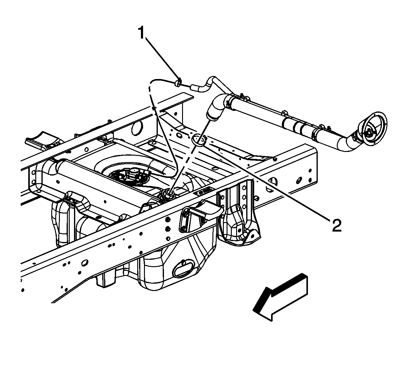
- Relieve the fuel system pressure. Refer to
Fuel Pressure Relief.
- Loosen the fuel fill pipe hose clamp (2) at the tank.
- Loosen the fuel vent pipe hose clamp (1) at the tank.
- Remove the fuel fill and vent hoses from the tank.
- Drain the fuel tank. Refer to
Fuel Tank Draining.
- Disconnect the fuel tank pressure sensor electrical connector.
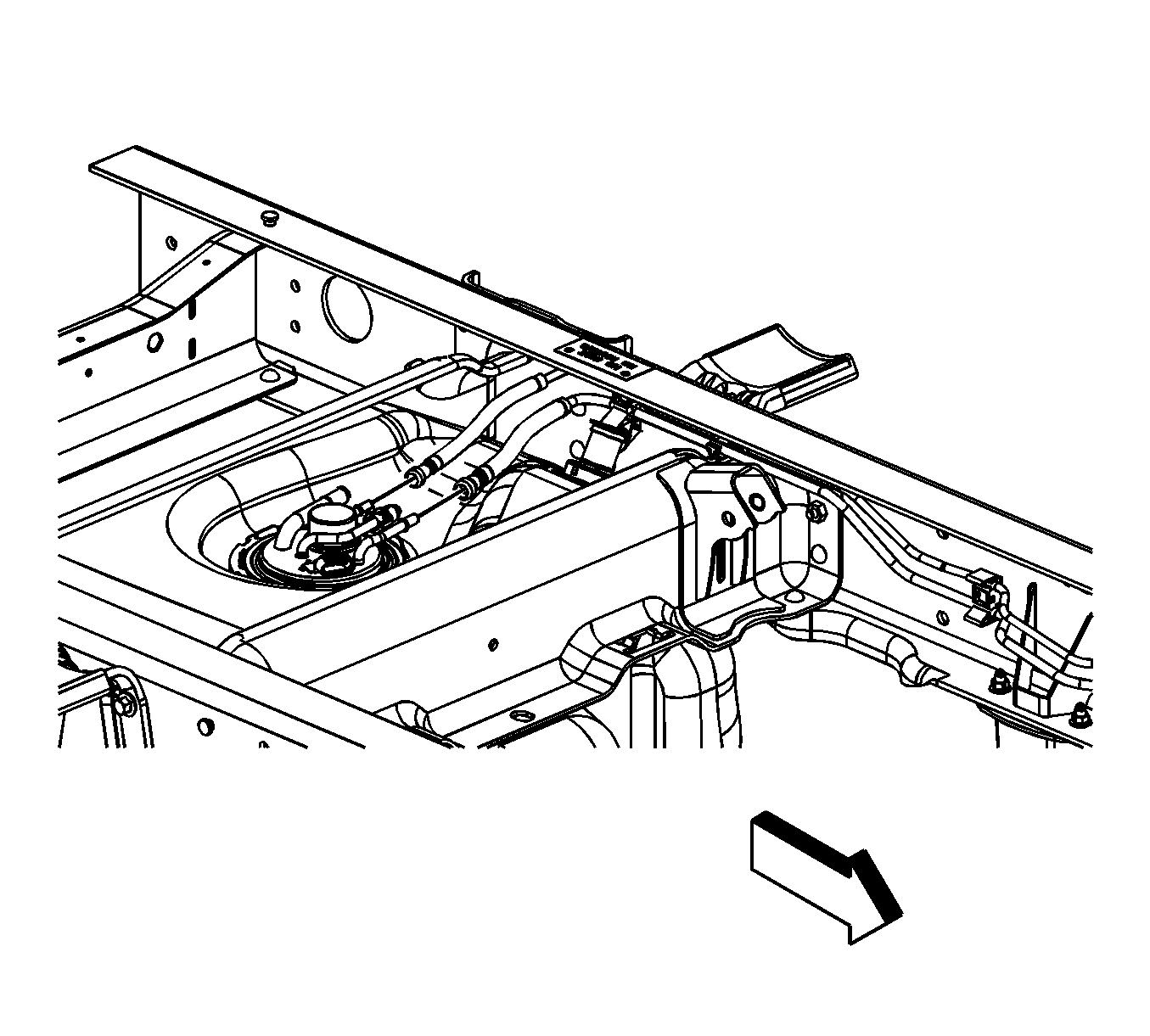
- Disconnect the fuel feed and EVAP (evaporative emission) quick connect fittings. Refer to
Metal Collar Quick Connect Fitting Service.
- Cap the fuel/EVAP lines in order to prevent possible system contamination.
- Raise and suitably support the vehicle. Refer to
Lifting and Jacking the Vehicle.
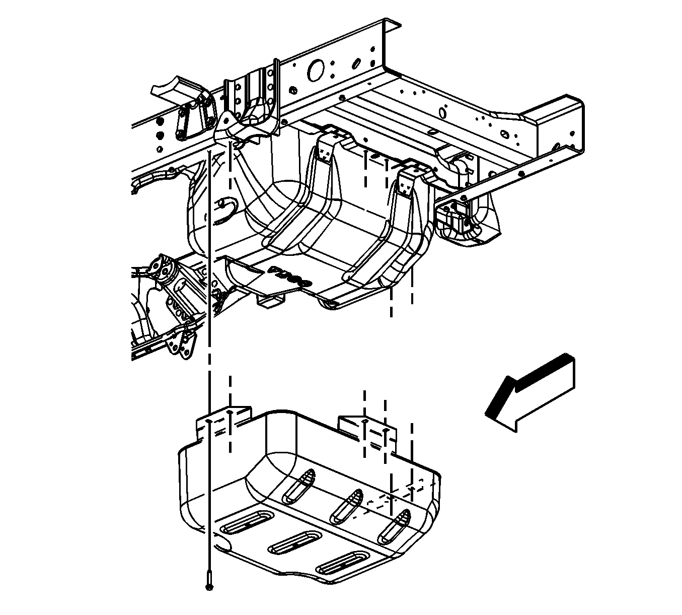
- Remove the fuel tank shield bolts.
- Remove the fuel tank shield.
- Place a suitable adjustable jack under the fuel tank.
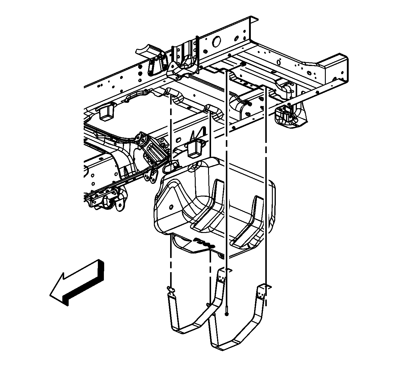
- Remove the fuel tank strap bolts.
- Remove the fuel tank straps.
- Lower the fuel tank.
- With the aid of an assistant, place the fuel tank in a suitable work area.
- If necessary, remove the sending unit. Refer to
Fuel Sender Assembly Replacement.
Installation Procedure

- If necessary, install the sending unit. Refer to
Fuel Sender Assembly Replacement.
- With the aid of an assistant, place the fuel tank on the jack.
- Raise the fuel tank.
Notice: Refer to Fastener Notice in the Preface section.
- Install the fuel tank straps.
- Install the fuel tank strap bolts.
Tighten
Tighten the bolts to 40 N·m (30 lb ft).
- Remove the jack from under the fuel tank.

- Install the fuel tank shield.
- Install the fuel tank shield bolts.
Tighten
Tighten the bolts to 18 N·m (13 lb ft).
- Lower the vehicle.

- Remove the caps from the fuel/EVAP lines.
- Connect the fuel feed and EVAP quick connect fittings. Refer to
Metal Collar Quick Connect Fitting Service.
- Connect the fuel tank pressure sensor electrical connector.

- Install the fuel fill and vent hoses to the tank.
- Tighten the fuel vent pipe hose clamp (1) at the tank.
- Tighten the fuel fill pipe hose clamp (2) at the tank.
Tighten
Tighten the clamps to 2.5 N·m (22 lb in).
- Refill the fuel tank.
- Install the fuel fill cap.
- Connect the negative battery cable. Refer to
Battery Negative Cable Disconnection and Connection.
- Perform the following steps in order to inspect for leaks.
| 19.1. | Turn the ignition ON, with the engine OFF, for 2 seconds. |
| 19.2. | Turn the ignition OFF for 10 seconds. |
| 19.3. | Turn the ignition ON, with the engine OFF. |
| 19.4. | Inspect for fuel leaks. |
Fuel Tank Replacement 1500 Crew Cab
Removal Procedure
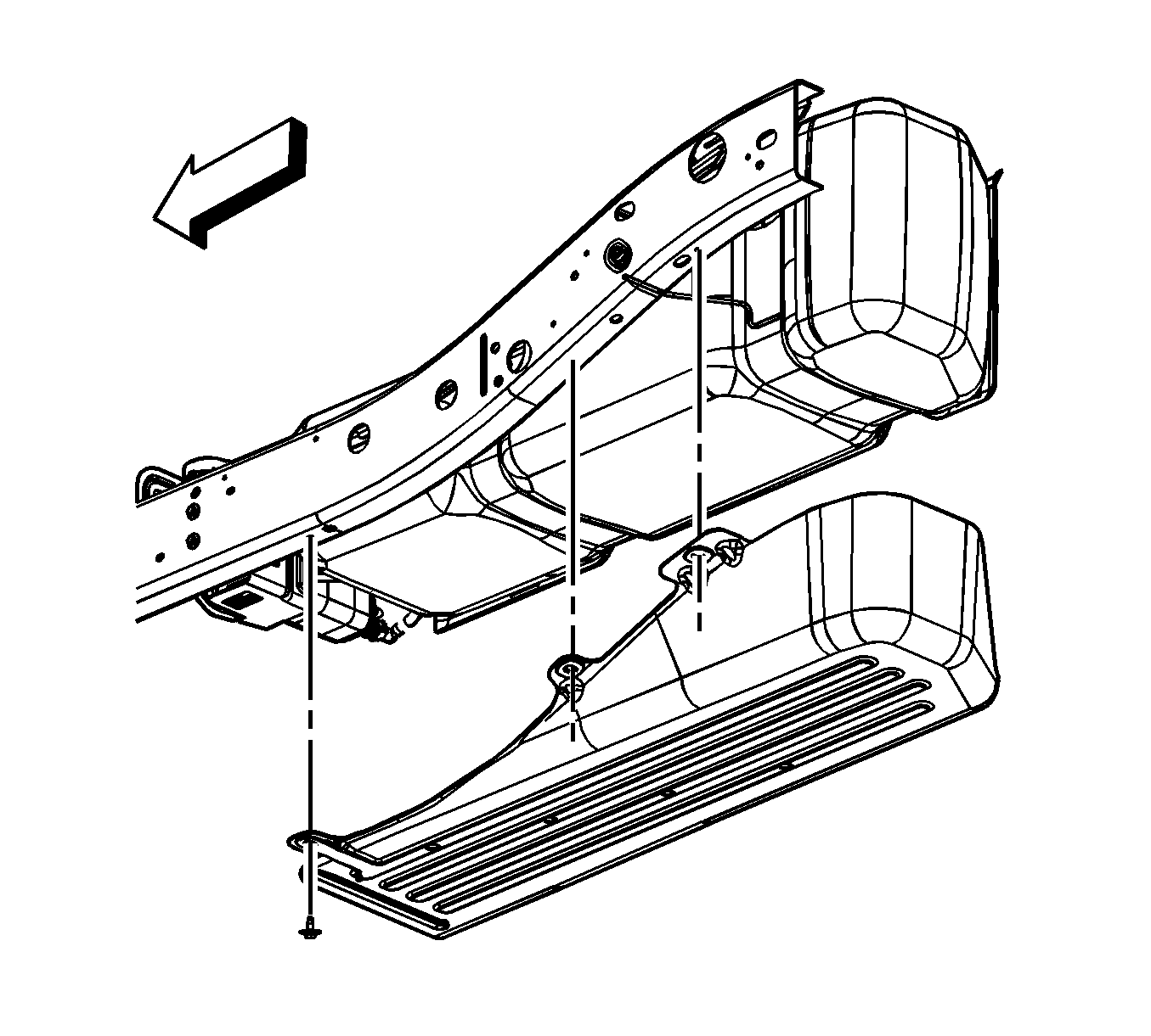
- Relieve the fuel system pressure. Refer to
Fuel Pressure Relief.
- Drain the fuel tank. Refer to
Fuel Tank Draining.
- Remove the fuel tank fill pipe. Refer to
Filler Tube Replacement.
- Remove the fuel tank shield bolts and shield, if necessary.
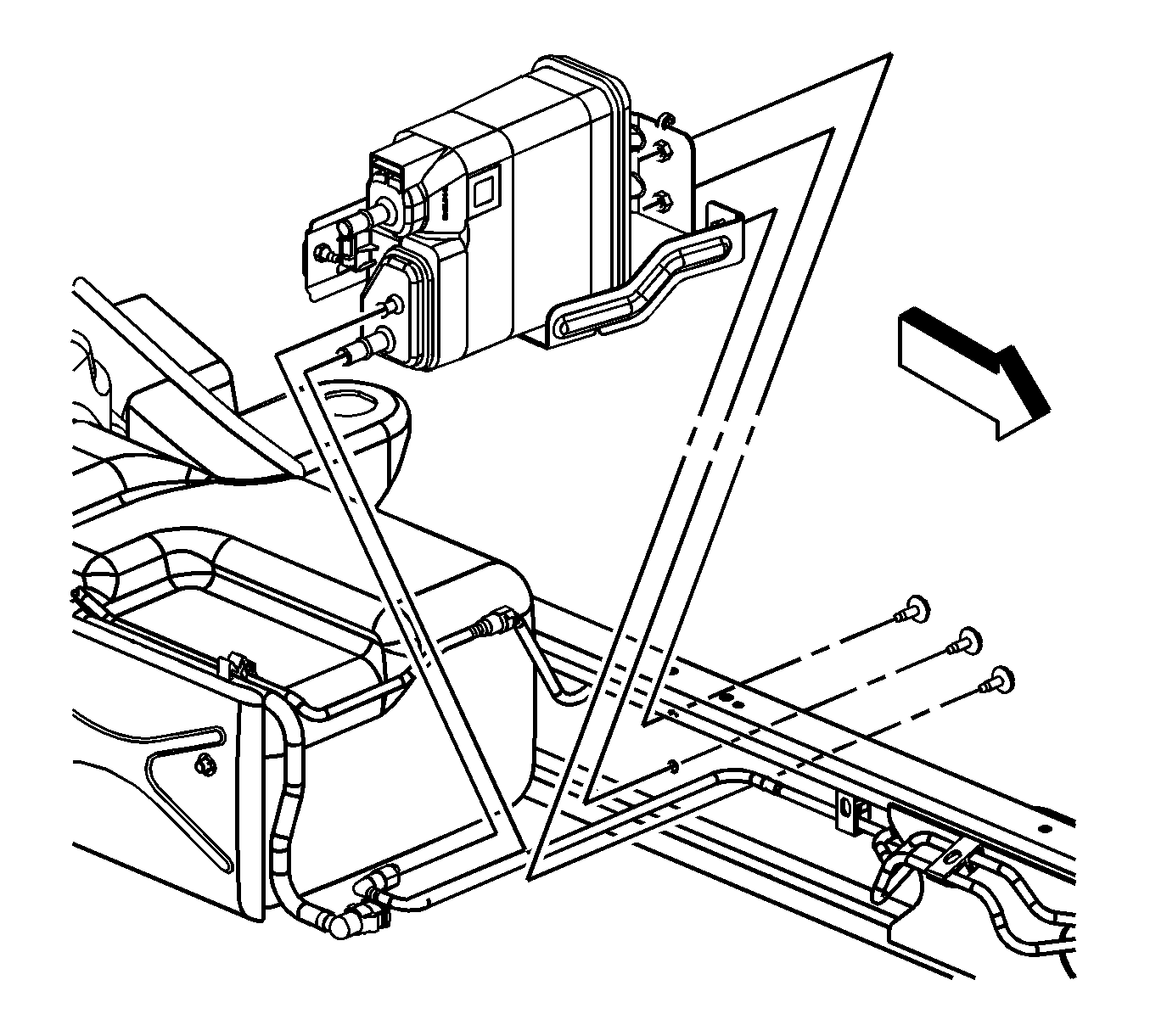
- Remove the evaporative emission (EVAP) canister. Refer to
Evaporative Emission Canister Replacement.
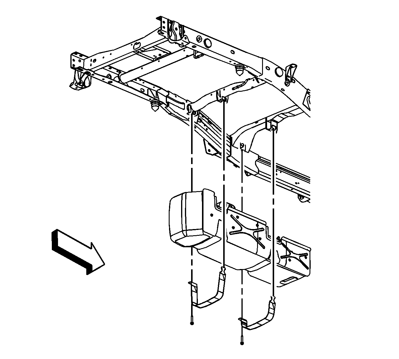
- Disconnect the fuel feed line from the tank. Refer to
Plastic Collar Quick Connect Fitting Service.
- Cap the fuel and EVAP lines in order to prevent possible system contamination.
- Place an adjustable jack under the fuel tank.
- Remove the fuel tank strap bolts.
- Remove the fuel tank straps.
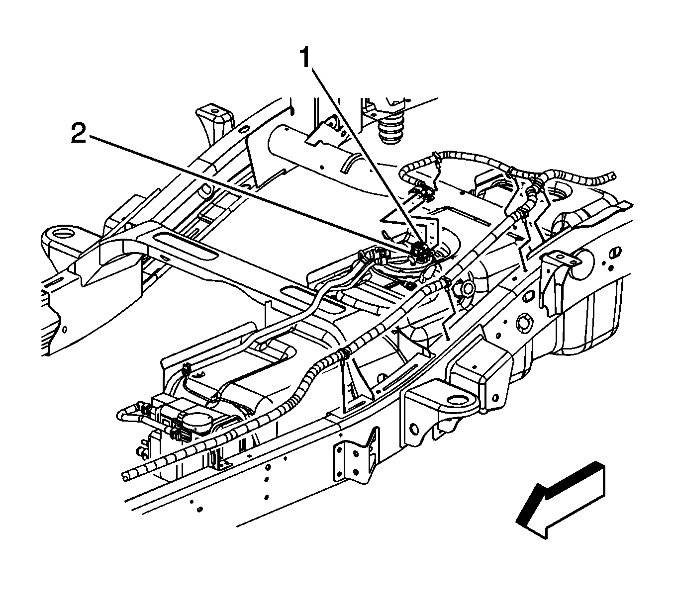
- Remove the harness clip from the frame.
- Lower the fuel tank under the electrical connectors are accessible.
- Disconnect the fuel tank pressure sensor (1) electrical connector.
- Disconnect the fuel tank sending unit (2) electrical connector, perform the following:
| 14.1. | Disengage the gray retainer. |
| 14.2. | Push down the black clip. |
| 14.3. | Disconnect the connector. |
- Completely lower the fuel tank.
- With the aid of an assistant, place the fuel tank in a suitable work area.
- If necessary, remove the sending unit. Refer to
Fuel Sender Assembly Replacement.
Installation Procedure

- If necessary, install the sending unit. Refer to
Fuel Sender Assembly Replacement.
- With the aid of an assistant, place the fuel tank on a adjustable jack.
- Raise the fuel tank until the electrical connections can be made.
- Connect the fuel tank sending unit (2) electrical connector. Engage the gray retainer.
- Connect the fuel tank pressure sensor (1) electrical connector.
- Completely raise the fuel tank.
- Install the harness clip to the frame.
Notice: Refer to Fastener Notice in the Preface section.

- Install the fuel tank straps.
- Install the fuel tank strap bolts.
Tighten
Tighten the bolts to 40 N·m (30 lb ft).
- Remove the adjustable jack from under the fuel tank.
- Remove the caps from the fuel and EVAP lines.
- Connect the fuel feed line at the tank. Refer to
Plastic Collar Quick Connect Fitting Service.

- Install the EVAP canister. Refer to
Evaporative Emission Canister Replacement.

- Install the fuel tank shield and bolts, if necessary.
Tighten
Tighten the bolts to 18 N·m (13 lb ft).
- Install the fuel tank fill pipe. Refer to
Filler Tube Replacement.
- Refill the fuel tank.
- Install the fuel cap.
- Connect the negative battery cable. Refer to
Battery Negative Cable Disconnection and Connection.
- Perform the following procedure in order to inspect for leaks:
| 19.1. | Turn the ignition ON, with the engine OFF, for 2 seconds. |
| 19.2. | Turn the ignition OFF for 10 seconds. |
| 19.3. | Turn the ignition ON, with the engine OFF. |
| 19.4. | Inspect for fuel leaks. |


