Removal Procedure
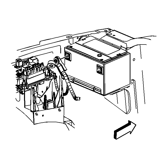
- Disconnect the negative battery cable . Refer to Battery Negative Cable Disconnection and Connection in Engine Electrical.
- Unsnap the positive battery cable cap.
- Loosen the positive battery cable bolt.
- Remove the positive battery cable.
- Remove the air cleaner outlet duct. Refer to Air Cleaner Outlet Duct Replacement .
- Remove the fuel fill cap in order to relieve the fuel pressure.
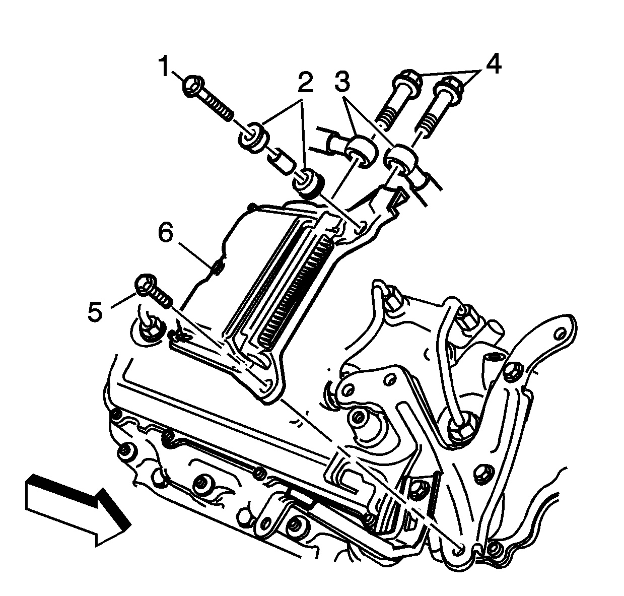
- Cut and discard the large tie straps from the control module (6) and harness.
- Remove the fuel line bolts (4) from the control module (6).
- Remove the control module bolts (1, 5).
- Remove the control module insulators (2) between the module and bracket.
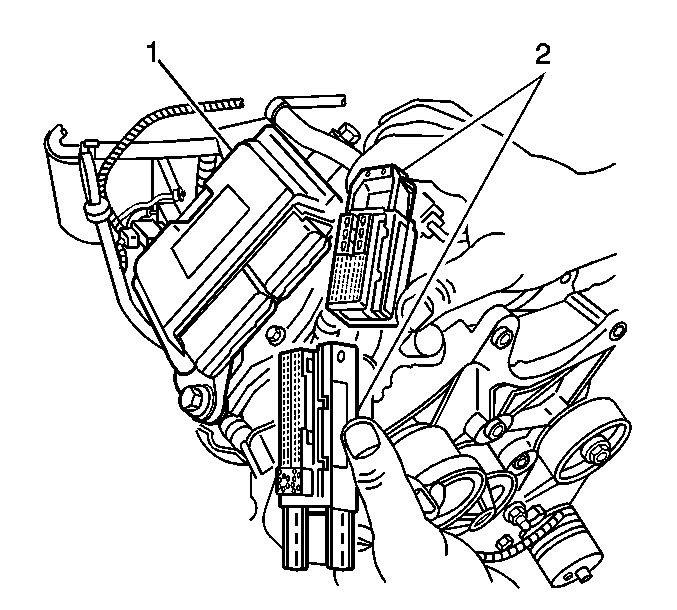
- Disconnect the control module electrical connectors (2).
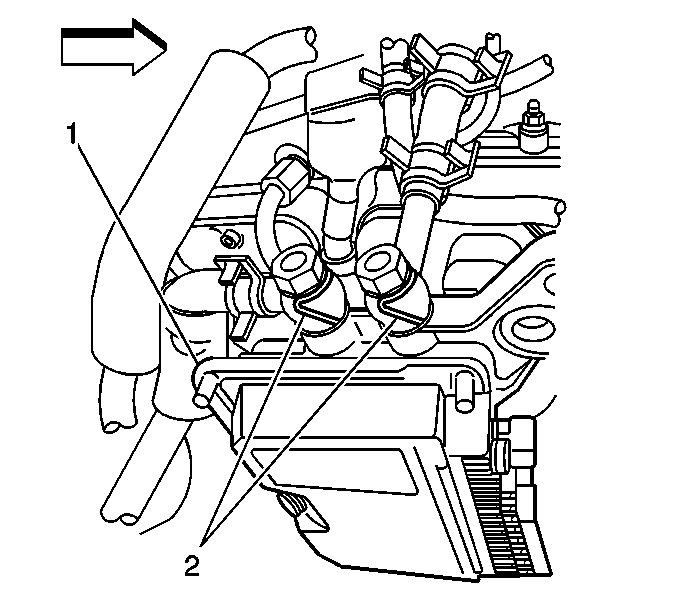
- Remove the fuel lines (2) from the control module (1) and discard washers.
- Remove the control module (1) from the bracket.


Important: Do not break off the tab on the electrical connector.

Installation Procedure
- Install the insulators (2) to the control module (6).
- Install the control module.
- Install by hand the fuel lines (2) and bolts with new washers to the control module (1).
- Install the control module bolts (1, 5).
- Connect the control module electrical connectors (2).
- Install the fuel line bolts (4) to the control module (6).
- Tighten the eyebolts (4).
- Install the air cleaner outlet duct. Refer to Air Cleaner Outlet Duct Replacement .
- Install the positive battery cable.
- Tighten the positive battery cable bolt.
- Snap the positive battery cable cap closed.
- Connect the negative battery cable . Refer to Battery Negative Cable Disconnection and Connection in Engine Electrical.
- Install the fuel fill cap.
- Depress the fuel manager primer button 30 times.
- Start the engine. If the engine stalls, repeat steps 13 and 15.
- Inspect for fuel leaks.

Important: Do not knock off the insulators when installing the fuel injector control module to the bracket.


Notice: Use the correct fastener in the correct location. Replacement fasteners must be the correct part number for that application. Fasteners requiring replacement or fasteners requiring the use of thread locking compound or sealant are identified in the service procedure. Do not use paints, lubricants, or corrosion inhibitors on fasteners or fastener joint surfaces unless specified. These coatings affect fastener torque and joint clamping force and may damage the fastener. Use the correct tightening sequence and specifications when installing fasteners in order to avoid damage to parts and systems.
Tighten
Tighten the bolts to 25 N·m (18 lb ft).


Tighten
Tighten the bolts to 35 N·m (26 lb ft).

Tighten
Tighten the bolt to 17 N·m (13 lb ft).
