Throttle Body Assembly Replacement With ETC
Removal Procedure
Notice: Handle the electronic throttle control components carefully. Use cleanliness in order to prevent damage. Do not drop the electronic throttle control components. Do not roughly handle the electronic throttle control components. Do not immerse the electronic throttle control components in cleaning solvents of any type.
Important: An eight digit part identification number is stamped on the throttle body casting. Refer to this number if servicing, or part replacement is required.
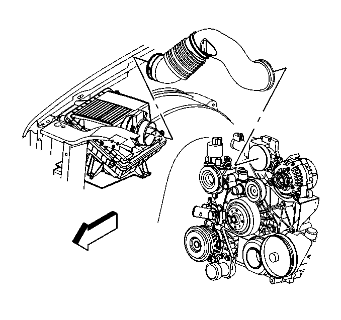
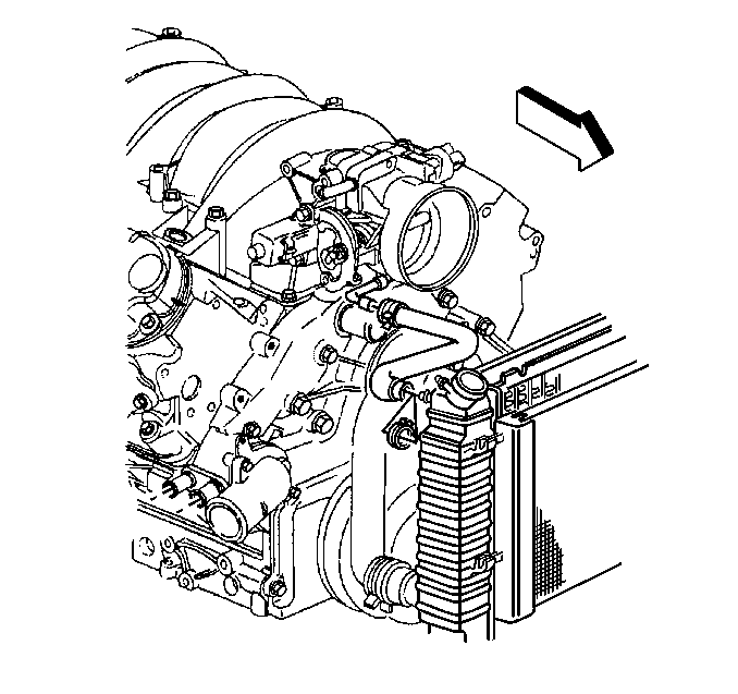
- Remove the air cleaner outlet duct. Refer to Air Cleaner Resonator Outlet Duct Replacement .
- If necessary, remove the engine sight shield. Refer to Upper Intake Manifold Sight Shield Replacement in Engine Mechanical-4.8L, 5.3L, and 6.0L.
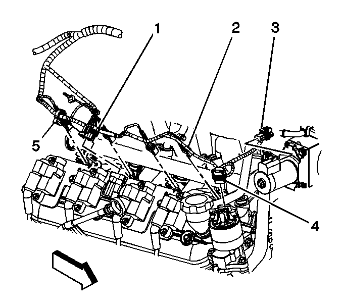
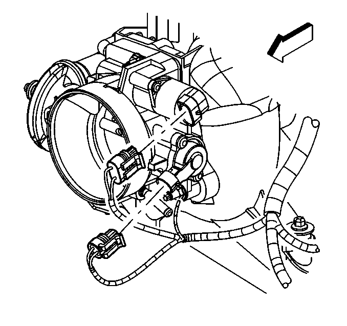
- Disconnect the throttle actuator motor electrical connector (3).
- Disconnect the throttle position (TP) sensor harness connector.
- Disconnect the crankcase ventilation hose from the throttle body.
- Remove the throttle body nuts.
- Disconnect the air bleed hose from the throttle body.
- Remove the throttle body and the gasket.
- Discard the throttle body gasket.
- Inspect the crankcase ventilation hose and the tube. Replace any damaged components.
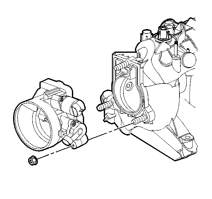
Important: Do not reuse the throttle body gasket. Install a new gasket during assembly.
Installation Procedure
- Install a new throttle body gasket.
- Connect the air bleed hose to the throttle body.
- Install the throttle body.
- Install the throttle body nuts.
- Connect the TP sensor harness connector.
- Connect the crankcase ventilation hose to the throttle body.
- Connect the throttle actuator motor electrical connector (3).
- Install the air cleaner outlet duct. Refer to Air Cleaner Resonator Outlet Duct Replacement .
- If necessary, install the engine sight shield. Refer to Upper Intake Manifold Sight Shield Replacement in Engine Mechanical-4.8L, 5.3L, and 6.0L.
- Connect a scan tool in order to test for proper throttle-opening and throttle-closing range.
- Verify that the vehicle meets the following conditions:
- Operate the accelerator pedal and monitor the throttle angles. The accelerator pedal should operate freely, without binding, between a closed throttle, and a wide open throttle (WOT).
- Start the engine.
- Check for coolant leaks.
Notice: Use the correct fastener in the correct location. Replacement fasteners must be the correct part number for that application. Fasteners requiring replacement or fasteners requiring the use of thread locking compound or sealant are identified in the service procedure. Do not use paints, lubricants, or corrosion inhibitors on fasteners or fastener joint surfaces unless specified. These coatings affect fastener torque and joint clamping force and may damage the fastener. Use the correct tightening sequence and specifications when installing fasteners in order to avoid damage to parts and systems.
Tighten
Tighten the nuts to 10 N·m (89 lb in).
Important: Verify that the throttle actuator motor harness connector and the connector seal are properly installed and not damaged.
| • | The vehicle is not in a reduced engine power mode. |
| • | The ignition is ON. |
| • | The engine is OFF. |
Throttle Body Assembly Replacement Without ETC
Removal Procedure
- Remove the air intake duct. Refer to Air Cleaner Resonator Outlet Duct Replacement .
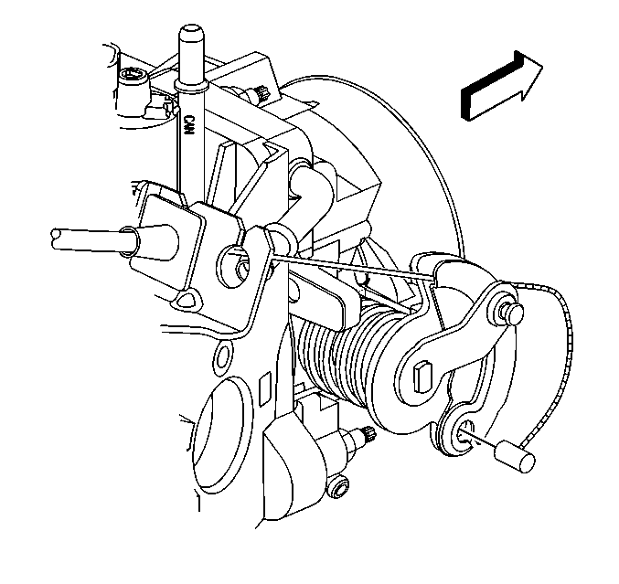
- Disconnect the accelerator control cable and the cruise control cable from the throttle body.
- Disconnect the vacuum hose from the throttle body.
- Disconnect the throttle position (TP ) sensor and idle air control (IAC) valve harness connectors.
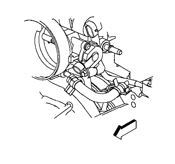
- Disconnect the coolant hose from the throttle body.
- Disconnect the coolant hose from the vapor vent pipe.
- Remove the throttle body attaching nuts.
- Remove the throttle body and the gasket. Discard the gasket.
- Clean the gasket sealing surfaces.
Notice: In order to prevent damage to the sealing surfaces, carefully use sharp tools in cleaning the old gasket from the aluminum surfaces.
Important:
• DO NOT soak the throttle body in a cold immersion type cleaner. The
throttle plate has a factory applied sealing compound. The DAG material
is applied to the outside edge of the plate and the throttle bore to
prevent air bypass at closed throttle. Strong solvents or brushing
removes the material. To clean the throttle body following disassembly,
use a spray type cleaner such as GM X-66A or GM P/N 1052626.
Use a shop towel to remove heavy deposits. • The TP sensor and the IAC valve are electrical components, and should
NOT come in contact with solvent or cleaner in order to avoid damage.
Installation Procedure
- Install the throttle body with a new gasket.
- Install the throttle body attaching nuts.
- Connect the coolant hose to the throttle body.
- Connect the coolant hose to the vapor vent pipe.
- Connect the accelerator control cable and the cruise control cable to the throttle body.
- Connect the TP sensor and the IAC valve electrical connectors.
- Connect the vacuum hose to the throttle body.
- Install the air intake duct. Refer to Air Cleaner Resonator Outlet Duct Replacement .
- With the engine OFF, verify that the accelerator pedal moves freely. Depress the accelerator pedal to the floor and release the pedal.
- In order to reset the IAC valve, perform the following procedure:
Notice: Use the correct fastener in the correct location. Replacement fasteners must be the correct part number for that application. Fasteners requiring replacement or fasteners requiring the use of thread locking compound or sealant are identified in the service procedure. Do not use paints, lubricants, or corrosion inhibitors on fasteners or fastener joint surfaces unless specified. These coatings affect fastener torque and joint clamping force and may damage the fastener. Use the correct tightening sequence and specifications when installing fasteners in order to avoid damage to parts and systems.
Tighten
Tighten the nuts to 10 N·m (89 lb in).
| 10.1. | Turn ON the ignition for 10 seconds. |
| 10.2. | Turn OFF the ignition for 5 seconds. |
| 10.3. | Start the engine and check for the proper idle speed. |
