Removal Procedure
- Remove the cylinder head assembly. Refer to Cylinder Head Replacement - Left Side or Cylinder Head Replacement - Right Side .
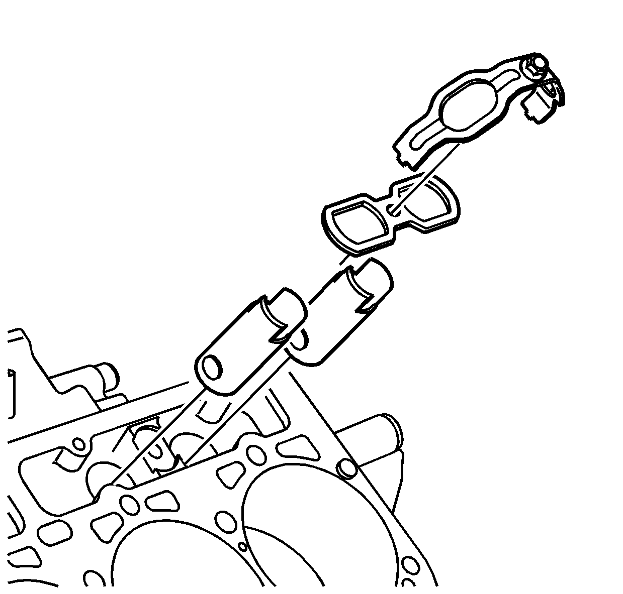
- Remove the valve lifter guide hold down bracket bolts.
- Remove the valve lifter guide hold down brackets.
- Remove the valve lifter guides.
- Remove the valve lifters.

Inspection and Repair
- Clean the valve lifter in suitable cleaning solvent and air dry.
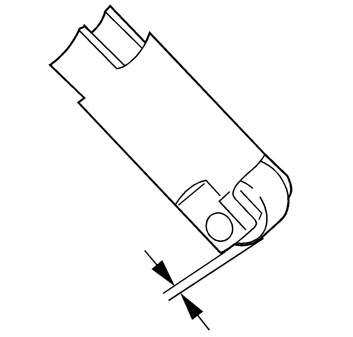
- Measure the roller protrusion from the valve lifter body.
- Replace the valve lifter assembly if the measurement value is less than the service limit.
- Inspect the valve lifters for the following:
- Inspect the valve lifter bore in the cylinder block for scuffing and wear.

The roller protrusion production valve is 0.989-1.0 mm (0.0389-0.0394 in) and service limit is over 0.9 mm (0.0354 in).
| • | The valve lifter body for scuffing and wear |
| • | The valve lifter roller assembly for wear |
| • | The valve lifter roller for smooth rotation |
Installation Procedure
- Apply clean engine oil to the roller and outside of the valve lifter assembly.
- Install the valve lifter.
- Install the valve lifter guides on the valve lifters.
- Install the guide hold down bracket.
- Install the valve lifter guide hold down bracket bolt.
- Install the cylinder head assembly. Refer to Cylinder Head Replacement - Left Side or Cylinder Head Replacement - Right Side .

Make sure that both tabs of the bracket on in the holes of the valve lifter guides.
Notice: Use the correct fastener in the correct location. Replacement fasteners must be the correct part number for that application. Fasteners requiring replacement or fasteners requiring the use of thread locking compound or sealant are identified in the service procedure. Do not use paints, lubricants, or corrosion inhibitors on fasteners or fastener joint surfaces unless specified. These coatings affect fastener torque and joint clamping force and may damage the fastener. Use the correct tightening sequence and specifications when installing fasteners in order to avoid damage to parts and systems.
Tighten
Tighten the hold down bracket bolt to 11 N·m (97 lb in).
