Removal Procedure
Important: Mark, sort, and organize all the components for assembly.
- Remove the valve rocker
arm cover. Refer to
Valve Rocker Arm Cover Replacement - Left Side
or
Valve Rocker Arm Cover Replacement - Right Side
.
- Remove the valve rocker arms.
- Remove the valve rocker
arm supports.
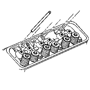
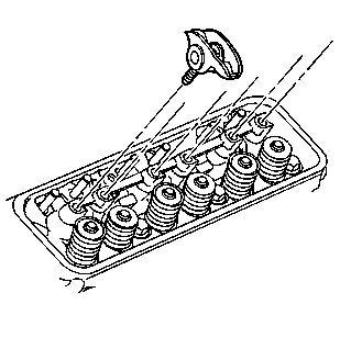
- Remove the valve pushrods.
- Clean and inspect the valver rocker arms and/or pushrods, if necessary.
Refer to
Valve Rocker Arm and Push Rod Cleaning and Inspection
in Engine Mechanical - 4.3L Unit Repair.
Installation Procedure
Important: Be sure to keep parts in order. Parts must be reinstalled into the original
location and position.
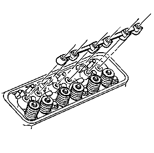
- Install the valve pushrods.
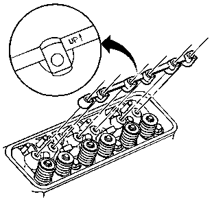
Important: Be sure that the arrow on the valve rocker arm support is in the up
position.
- Install the valve rocker arm supports.
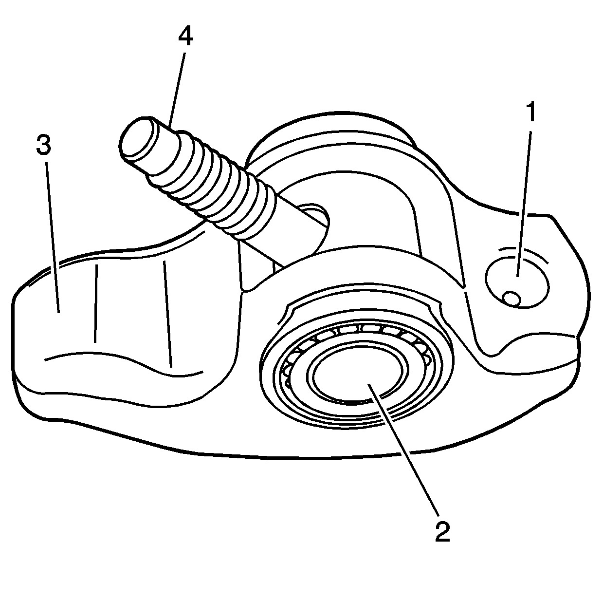
- Apply lubricant GM U.S. P/N 12345501,
Canada P/N 992704, or equivalent to the following valve rocker
arm contact surfaces:
| • | Valve pushrod socket (1) |
Notice: Use the correct fastener in the correct location. Replacement fasteners
must be the correct part number for that application. Fasteners requiring
replacement or fasteners requiring the use of thread locking compound or sealant
are identified in the service procedure. Do not use paints, lubricants, or
corrosion inhibitors on fasteners or fastener joint surfaces unless specified.
These coatings affect fastener torque and joint clamping force and may damage
the fastener. Use the correct tightening sequence and specifications when
installing fasteners in order to avoid damage to parts and systems.
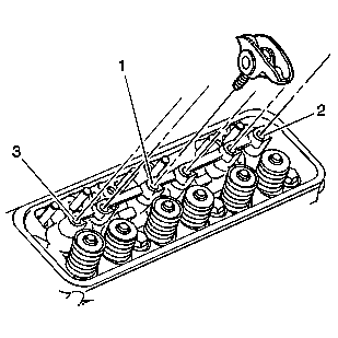
- Install the valve rocker arms as follows:
| 4.1. | Finger start the bolt at location (1) |
| 4.2. | Finger start the bolt at location (2) |
| 4.3. | Finger start the bolt at location (3) |
| 4.4. | Finger start the remaining valve rocker arm bolts |
- Rotate the crankshaft
balancer to position the crankshaft balancer alignment mark (1) 57-63 degrees
clockwise or counterclockwise from the engine front cover alignment tab
(2).
Important: Once the valve rocker arms are installed and properly torqued, no additional
valve lash adjustment is required.
- Tighten the valve rocker arm bolts.
Tighten
Tighten valve rocker arm bolts to 30 N·m (22 lb ft).
- Install the valve rocker arm cover. Refer to
Valve Rocker Arm Cover Replacement - Left Side
or
Valve Rocker Arm Cover Replacement - Right Side
