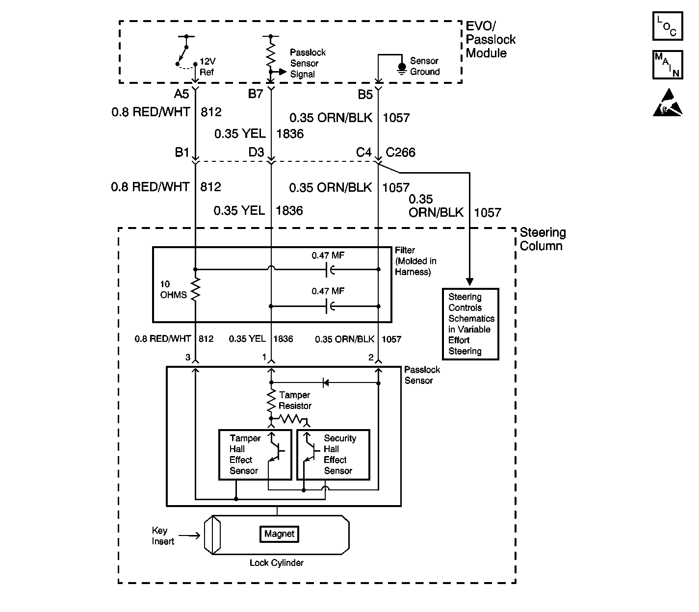
Circuit Description
The Passlock™ system is designed to prevent engine operation if the correct key is not used to start the vehicle. As the ignition key turns the lock cylinder, cylinder rotation produces an analog voltage code in the Passlock™ sensor.
The EVO/Passlock™ module receives this voltage code and is compared to the last learned voltage code. If the codes match, the EVO/Passlock™ module sends a class 2 message to the VCM/PCM, enabling the fuel injectors.
Diagnostic Aids
You must perform the Diagnostic System Check prior to diagnosing any symptom or any Diagnostic Trouble Code table. Diagnose the DTCs in the order specified in the Passlock™ System DTC list. Failure to do so may result in the following conditions:
| • | Extended diagnostic time |
| • | Incorrect diagnosis |
| • | Incorrect parts replacement |
If an EVO/Passlock™ module, a passlock™ sensor, or the VCM/PCM have been replaced, perform a learn procedure before following the Diagnostic System Check.
Important: On vehicles equipped with diesel engines, if you are instructed in any Theft Deterrent System test to start the vehicle you must always wait for the "Wait to Start" indicator to turn off prior to cranking the engine. This process could take anywhere from 2 to 17 seconds.
Test Description
The numbers below refer to the step numbers on the diagnostic table.
-
Lack of communication may be due to a partial malfunction of the class 2 serial data circuit or due to a total malfunction of the class 2 serial data circuit. The specified procedure will determine the particular condition.
-
Tests for an open in the passlock™ sensor signal circuit which may not set a DTC (B2958) under certain conditions.
-
The presence of DTCs which begin with "U" indicate some other module is not communicating. The specified procedure will compile all the available information before tests are performed.
Step | Action | Value(s) | Yes | No |
|---|---|---|---|---|
1 | Install a scan tool. Does the scan tool power up? | -- | Go to Step 2 | Go to Scan Tool Does Not Power Up in Data Link Communications |
Does the scan tool communicate with the EVO/Passlock™ Module and the PCM/VCM? | -- | Go to Step 3 | Go to Scan Tool Does Not Communicate with Class 2 Device in Data Link Communications | |
3 | Select the EVO/Passlock™ Module display DTCs function on the scan tool. Does the scan tool display any DTCs? | -- | Go to Step 5 | Go to Step 4 |
Does the scan tool display OPEN? | -- | Go to Symptoms | ||
Does the scan tool display any DTCs which begin with a "U"? | -- | Go to Scan Tool Does Not Communicate with Class 2 Device in Data Link Communications | Go to Step 6 | |
6 | Does the scan tool display DTC B0688, B2947, B2948, B2957, B2958, B2960, B3031, B3033, or C0559? | -- | System OK |
