DTC P0712 Transmission Fluid Temperature (TFT) Sensor Circuit Low Input 5.7L and 7.4L Gas
Circuit Description
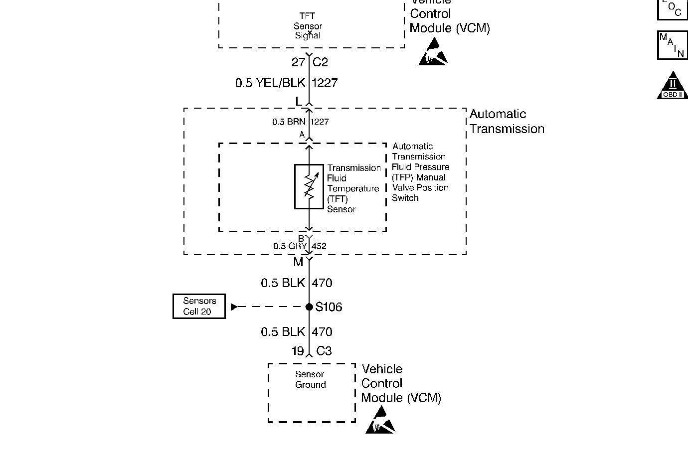
The Transmission Fluid Temperature (TFT) is a thermistor that controls the signal voltage to the VCM. The VCM supplies a 5 volt reference signal to the sensor on circuit 1227. When the transmission fluid is cold, the sensor resistance is high. The VCM detects high signal voltage. As the transmission fluid temperature increases to normal operating temperature, the sensor resistance becomes less, and the voltage decreases to 1.5-2 volts.
When the VCM detects a continuous short to ground in the TFT Sensor or signal circuit, then DTC P0712 sets. DTC P0712 is a type D DTC. For California emission vehicles, DTC P0712 is a type B DTC.
Conditions for Setting the DTC
| • | The ignition is ON. |
| • | The TFT Sensor indicates a voltage of less than 0.2 volts. |
| • | All conditions met for 10 seconds. |
Action Taken When the DTC Sets
| • | The transmission default temperature is 140° C (275° F). The scan tool does not display the default temperature. |
| • | VCM freezes shift adapts from being updated. |
| • | For California Emissions only, the VCM illuminates the Malfunction Indicator Lamp (MIL). |
Conditions for Clearing the MIL/DTC
| • | For California Emissions only, the VCM turns off the MIL after three consecutive ignition cycles without a failure reported. |
| • | A scan tool can clear the DTC from the VCM history. The VCM clears the DTC from the VCM history if the vehicle completes 40 warm-up cycles without a failure reported. |
| • | The VCM cancels the DTC default actions when the fault no longer exists and the ignition cycles OFF long enough to power down the VCM. |
Diagnostic Aids
| • | With a transmission fluid over temperature DTC P1812 also set, inspect the transmission cooling system. |
| • | Inspect the harness routing for a potential short to ground in circuit 1227. |
| • | Inspect the wiring for poor electrical connections at the VCM. Inspect the wiring for poor electrical connections at the transmission 20-way connector. Look for the following conditions: |
| - | A bent terminal |
| - | A backed out terminal |
| - | A damaged terminal |
| - | Poor terminal tension |
| - | A chafed wire |
| - | A broken wire inside the insulation |
| • | When diagnosing for an intermittent short or open condition, massage the wiring harness while watching the test equipment for a change. |
| • | Test the TFT Sensor at various temperatures in order to evaluate the possibility of a "skewed" (mis-scaled) sensor. Use the temperature to resistance value scale. A "skewed" sensor may cause delayed garage shifts or TCC complaints. |
| • | Verify the customer driving habits, trailer towing, weight, or towing in Overdrive. |
| • | First diagnose and clear any engine DTCs or TP Sensor codes that are present. Then inspect for any transmission DTCs that may have reset. |
Test Description
The numbers below refer to the step numbers on the diagnostic table.
-
This step tests for a short to ground or a skewed sensor by verifying the fault still exists.
-
This step tests for an internal fault within the transmission by creating an open.
Step | Action | Value(s) | Yes | No |
|---|---|---|---|---|
1 | Was the Powertrain On-Board Diagnostic (OBD) System Check performed? | -- | ||
2 | Perform the transmission fluid checking procedure. Refer to Transmission Fluid Check . Did you perform the fluid checking procedure? | -- | Go to Transmission Fluid Check | |
Important: Before clearing the DTCs, use the scan tool in order to record the Freeze Frame and Failure Records for reference. The Clear Info function will erase the data. Does the scan tool display a TFT Sensor signal voltage less than the specified value? | 0.2 volts | Go to Diagnostic Aids | ||
Does the scan tool display a TFT Sensor signal voltage greater than the specified value? | 4.92 volts | |||
5 |
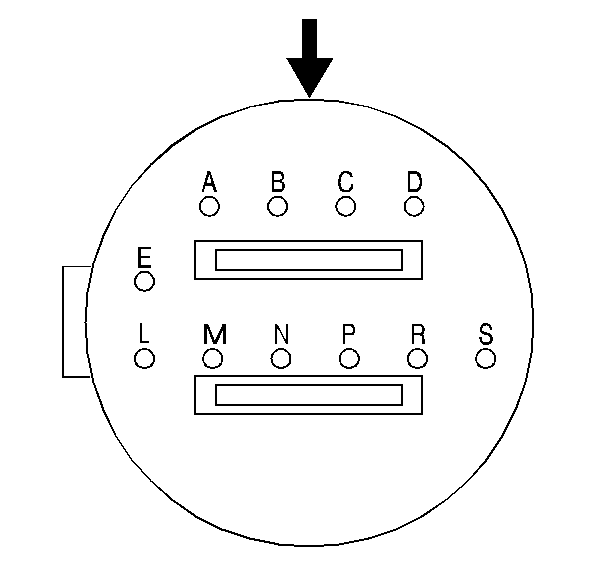
Automatic Transmission Connector End View Refer to Electronic Component Description . Is the resistance within specifications? | 16,000ohms at -10°C (50°F) to 133ohms at 110°C (230°F) | Go to Diagnostic Aids | |
6 |
Refer to Transmission Oil Pan Removal, in On-Vehicle Service. Refer to Electrical Diagnosis, Section 8. Did you find a problem? | -- | ||
7 |
Refer to TFT Sensor portion of Electronic Component Description . Is the resistance within specifications? | 16,000ohms at -10°C (50°F) to 133ohms at 110°C (230°F) | Go to Diagnostic Aids | |
8 | Replace the internal wiring harness. Refer to Automatic Transmission Internal Wiring Harness Assembly Replacement, in On-Vehicle Service. Is the replacement complete? | -- | -- | |
9 | Inspect circuit 1227 for a short to ground. Refer to Electrical Diagnosis, Section 8. Did you find a problem? | -- | ||
10 | Inspect the VCM for faulty connections. Did you find a problem? | -- | ||
11 | Replace the VCM. Refer to VCM Replacement/Programming , Section 6. Is the replacement complete? | -- | -- | |
12 | In order to verify your repair, perform the following procedure:
Has the test run and passed? | -- | System OK |
DTC P0712 Transmission Fluid Temperature (TFT) Sensor Circuit Low Input 6.5L Diesel
Circuit Description
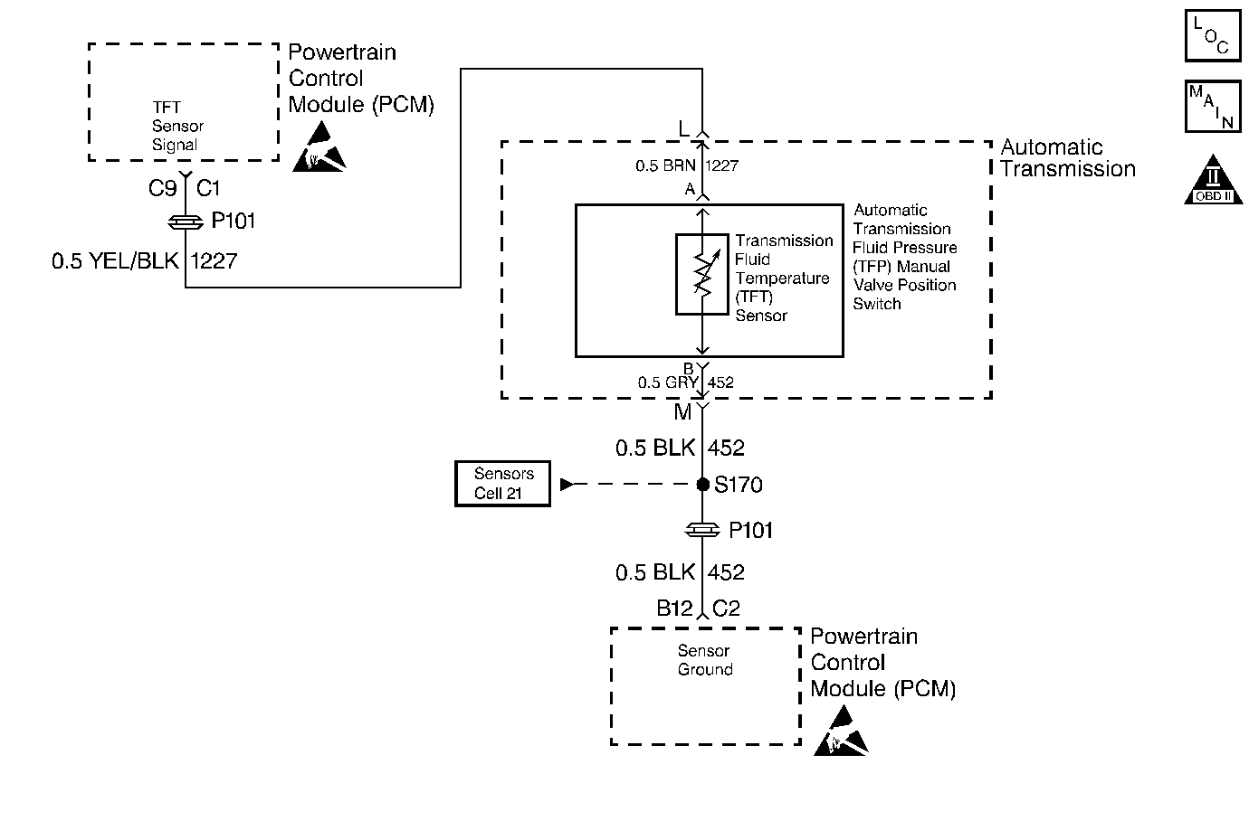
The Transmission Fluid Temperature (TFT) is a thermistor that controls the signal voltage to the PCM. The PCM supplies a 5 volt reference signal to the sensor on circuit 1227. When the transmission fluid is cold, the sensor resistance is high. The PCM detects high signal voltage. As the transmission fluid temperature increases to the normal operating temperature, the sensor resistance becomes less, and the voltage decreases to 1.5-2 volts.
When the PCM detects a continuous short to ground in the TFT Sensor or signal circuit, then DTC P0712 sets. DTC P0712 is a type B DTC.
Conditions for Setting the DTC
| • | The ignition is ON. |
| • | The TFT Sensor indicates a voltage of less than 0.3 volts. |
| • | All conditions met for 10 seconds. |
Action Taken When the DTC Sets
| • | The transmission default temperature is 140° C (275° F). The scan tool does not display the default temperature. |
| • | The PCM illuminates the Malfunction Indicator Lamp (MIL). |
Conditions for Clearing the MIL/DTC
| • | The PCM turns off the MIL after three consecutive ignition cycles without a failure reported. |
| • | A scan tool can clear the DTC from the PCM history. The PCM clears the DTC from the PCM history if the vehicle completes 40 warm-up cycles without a failure reported. |
| • | The PCM cancels the DTC default actions when the fault no longer exists and the ignition cycles OFF long enough to power down the PCM. |
Diagnostic Aids
| • | With a transmission fluid over temperature DTC P1812 also set, inspect the transmission cooling system. |
| • | Inspect the harness routing for a potential short to ground in circuit 1227. The scan tool TFT Sensor display should rise steadily, then stabilize. |
| • | Inspect the wiring for poor electrical connections at the PCM. Inspect the wiring for poor electrical connections at the transmission 20-way connector. Look for the following conditions: |
| - | A bent terminal |
| - | A backed out terminal |
| - | A damaged terminal |
| - | Poor terminal tension |
| - | A chafed wire |
| - | A broken wire inside the insulation |
| • | When diagnosing for an intermittent short or open condition, massage the wiring harness while watching the test equipment for a change. |
| • | Test the TFT Sensor at various temperatures in order to evaluate the possibility of a "Skewed" (mis-scaled) sensor. Use the temperature to resistance value scale. A "skewed" sensor may cause delayed garage shifts or TCC complaints. |
| • | Verify the customer driving habits, trailer towing, weight, or towing in Overdrive. |
| • | First diagnose and clear any engine DTCs or APP Sensor codes that are present. Then inspect for any transmission DTCs that may have reset. |
Test Description
The numbers below refer to the step numbers on the diagnostic table.
-
This step tests for a short to ground or a "skewed" sensor by verifying the fault still.
-
This step tests for an internal fault within the transmission by creating an open.
Step | Action | Value(s) | Yes | No |
|---|---|---|---|---|
1 | Was the Powertrain On-Board Diagnostic (OBD) System Check performed? | -- | ||
2 | Perform the transmission fluid checking procedure. Refer to Transmission Fluid Check . Did you perform the fluid checking procedure? | -- | -- | |
Important: Before clearing the DTCs, use the scan tool in order to record the Freeze Frame and Failure Records for reference. The Clear Info function will erase the data. Does the scan tool display a TFT signal voltage less than the specified value? | 0.2 volts | Go to Diagnostic Aids | ||
Does the scan tool display a TFT signal voltage greater than the specified value? | 4.92 volts | |||
5 |
Automatic Transmission Connector End View Refer to Electronic Component Description . Is the resistance within specifications? | 16,000ohms at -10°C (50°F) to 133ohms at 110°C (230°F) | Go to Diagnostic Aids | |
6 |
Refer to Transmission Oil Pan Removal, in On-Vehicle Service. Refer to Electrical Diagnosis, Section 8. Did you find a problem? | -- | ||
7 |
Refer to the TFT Sensor section of Electronic Component Description . Is the resistance within specifications? | 16,000ohms at -10°C (50°F) to 133ohms at 110°C (230°F) | Go to Diagnostic Aids | |
8 | Replace the internal wiring harness. Refer to Automatic Transmission Wiring Harness Assembly Replacement, in On-Vehicle Service. Is the replacement complete? | -- | -- | |
9 | Inspect circuit 1227 for a short to ground. Refer to Electrical Diagnosis, Section 8. Did you find a problem? | -- | ||
10 | Inspect the PCM for faulty connections. Did you find a problem? | -- | ||
11 | Replace the PCM. Refer to Powertrain Control Module Replacement/Programming , Section 6. Is the replacement complete? | -- | -- | |
12 | In order to verify your repair, perform the following procedure:
Has the test run and passed? | -- | System OK |
