POWER STEERING PUMP LEAKS INCORRECT BELT TENSIONING

MODELS: 1985-1986 C,K,P-2500-3500 SERIES TRUCKS EOUIPPED WITH 7.4L (454) ENGINE AND H5D HEAVY DUTY FEDERAL EMISSIONS
Some power steering pumps on 1985-1986 C, K, P - 2500, 3500 series trucks equipped with 7.4L (454) engines and H5D heavy duty Federal Emissions may leak steering fluid. Power steering pump leakage on these models may be attributed to the A.I.R. pump belt tension being too fight. Excessive tension causes an increased load on the bushing and seal of the power steering pump which may eventually result in a leaky pump. To correct this condition, the tension of the single drive belt between the A.I.R. pump and power steering pump should be fightened to 250 Newtons, instead of 650 Newtons as specified in the service manual. The proper procedure for tensioning this belt is outlined below. Power steering pumps which exhibit fluid leakage at front seal should be replaced.
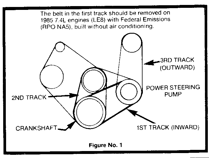
On some 1985 models without air conditioning (RPO C60 and C69), a drive belt was also incorrectly installed in the No. 1 track (Figure No. 1) during production. With this belt installed, it restricts the movement of the power steering pump. The pump is used for adjusting the tension of the belts in the No. 2 and No. 3 tracks. This lack of adjustment requires excessive tension to be placed on the power steering pump belt in order to adjust the other belts to their proper tensions. Because of the restriction that the belt in the No. 1 track causes, it must be removed and discarded. With this belt removed, the normal operations of the engine will not be affected.
BELT TENSION ADJUSTMENT PROCEDURE
1. Loosen the A.I.R. pump pivot and adjustment bolts.
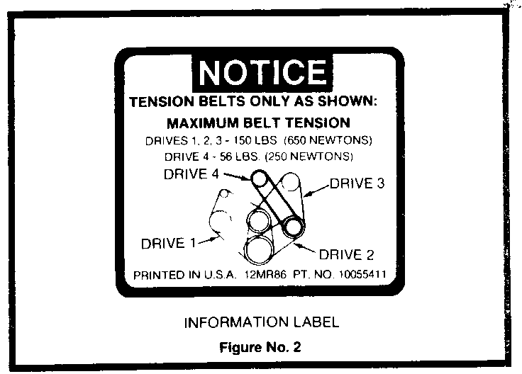
2. Place a belt tension gage J-23600-B or equivalent, midway in the drive belt No. 4 (Figure No.2).
3. Adjust No. 4 drive belt so that the tension on the belt is 250 Newtons (56 pounds).
4. Finger tighten the two A.I.R. pump bolts, while maintaining belt tension.
5. Torque the A.I.R. pump pivot and adjustment bolts to 33 N.m (24 lb. ft.).
6. Inspect the belt tension and remove belt tension gage.
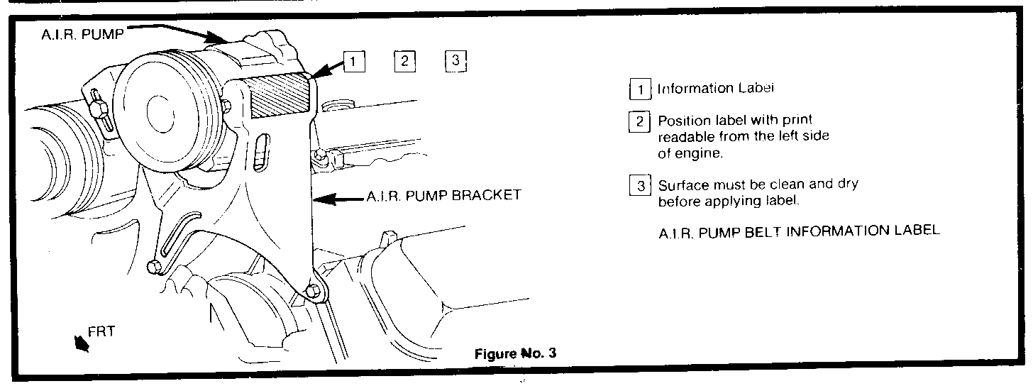
7. Clean and dry the A.I.R. pump support bracket area shown in Figure No. 3.
8. Apply the information label P/N 10055411 to the A.I.R. pump support bracket (Figure No. 3).


General Motors bulletins are intended for use by professional technicians, not a "do-it-yourselfer". They are written to inform those technicians of conditions that may occur on some vehicles, or to provide information that could assist in the proper service of a vehicle. Properly trained technicians have the equipment, tools, safety instructions and know-how to do a job properly and safely. If a condition is described, do not assume that the bulletin applies to your vehicle, or that your vehicle will have that condition. See a General Motors dealer servicing your brand of General Motors vehicle for information on whether your vehicle may benefit from the information.
