POSSIBLE FRAME CRACK PART # AND REPAIR PROCEDURE

MODELS: 1985-86 K1 AND 1987 V1 TRUCKS
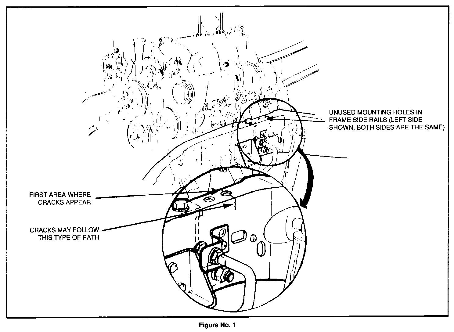
Under severe vehicle usage operations, some 1985-86 K1 and 1987 V1 trucks may exhibit a frame crack at the unused holes between the front shock and engine mount (See Figure 1). The crack may start at the top flange.
If this condition is encountered, the crack should be cleaned and welded and both frame rails repaired using the following parts and procedures.
Parts Information
Part Number Description ------------ ------------ 15646904 Kit - Containing right & left frame brace and attaching parts and graphics.
Parts are expected to be available on October 30, 1989. Until then normal part orders will not be accepted by GMSPO. Only verifiable emergency VIP orders will be accepted. SPO will make every effort to obtain parts. All parts will be placed on 400 control to waive VIP surcharges. However, the part will be shipped premium transportation at dealer's expense. All other order types will be canceled as incorrectly ordered while the 400 control is in place.
Welding Procedure
(See Step 4 in Left Hand and Step 6 in Right Hand Bracket Installation Procedures)
When gas metal arc welding (GMAW), use Electrode E705-3.
When shielded metal arc welding (SMAW), use Electrode E7018.
* Clean as necessary with a stiff wire brush and a clean rag.
* Determine the inner end(s) of the crack by cleaning and grinding the surface.
* Drill a 1/8" hole at the end(s) of crack as an aid to stop crack progress.
* Grind a V-groove along entire length of crack.
* Weld the V-groove completely, filling the entire length past the hole(s) by 1/4".
* Grind smooth to allow tight reinforcement fit.
Right-Hand Reinforcement Bracket Installation
CAUTION:
PROPER EYE PROTECTION IS REQUIRED AT ALL TIMES WHEN PERFORMING THE FOLLOWING PROCEDURES.
1. Disconnect batteries.
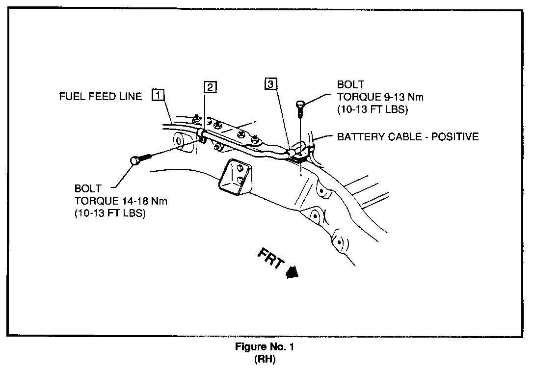
2. Remove retainer clips (2) and (3) from fuel feed line (1) at right-hand frame rail. Refer to Figure 1 RH.
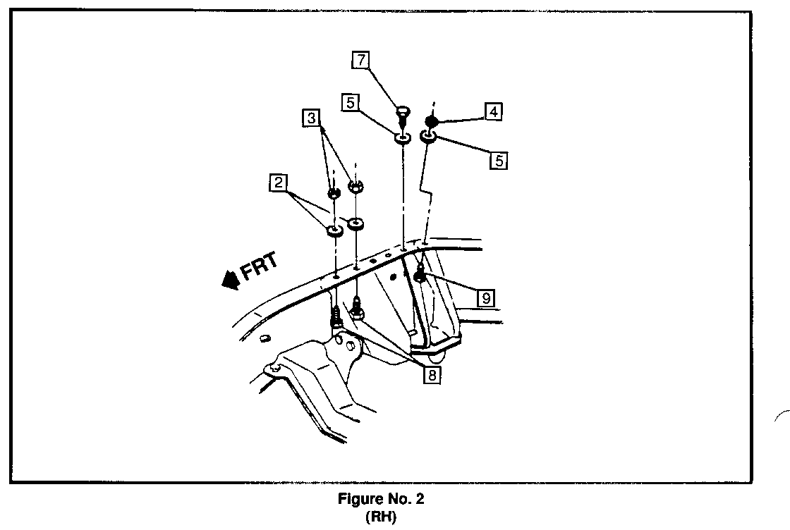
3. Remove existing nuts (3), washers (2), and bolts (8). DISCARD. Refer to Figure 2 RH.
4. Remove existing nut (4), washer (5), and bolt (9). DISCARD. Refer to Figure 2 RH.
5. Remove existing bolt (7) and washer (5). DISCARD. Refer to Figure 3 RH.
6. Weld crack using welding procedure, if necessary.
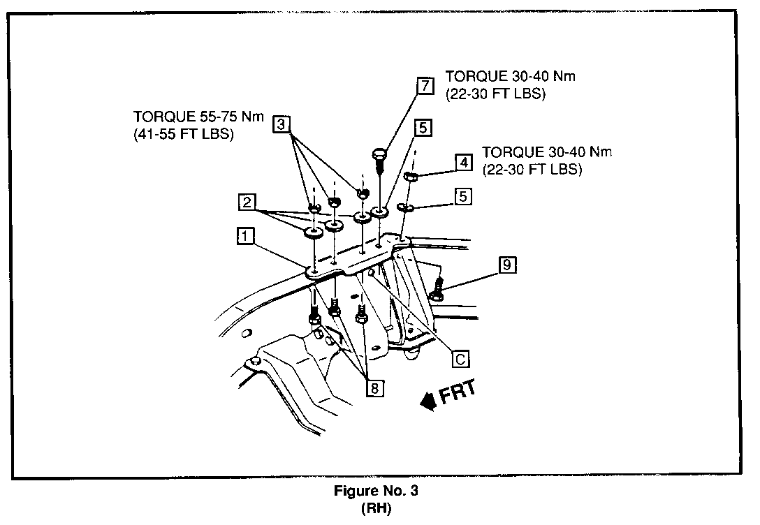
7. Position bracket (1) on top flange area of frame rail. Refer to Figure 3 RH.
8. Install new bolts (8), washers (2), and nuts (3). Torque nuts (3) to 55-75 Nm (41-55 lbs/ft). Refer to Figure 3 RH.
9. Install new bolt (9), washer (5), and nut (4). Torque nut (4) to 30-40 Nm (22-30 lbs/ft). Refer to Figure 3 RH.
10. Install new bolt (7) and washer (5). Torque bolt (7) to 30-40 Nm (22-30 lbs/ft). Refer to Figure 3 RH.
11. Using bracket (1) as a template, enlarge hole C with 15/32" diameter high speed drill. Access through right-hand wheel opening is suggested. Refer to Figure 3 RH.
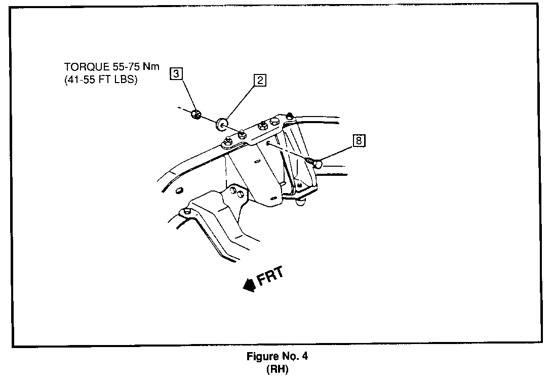
12. Install bolt (8), washer (2), and nut (3). Torque nut (3) to 55-75 Nm (41-55 lbs/ft). Refer to Figure 4 RH.
13. Position fuel feed line (1) and install retainer clips (2) and (3). Refer to Figure 1 RH.
Left Hand Reinforcement Bracket Installation
CAUTION:
PROPER EYE PROTECTION IS REQUIRED AT ALL TIMES WHEN PERFORMING THE FOLLOWING PROCEDURES.
1. Ensure that batteries are still disconnected.
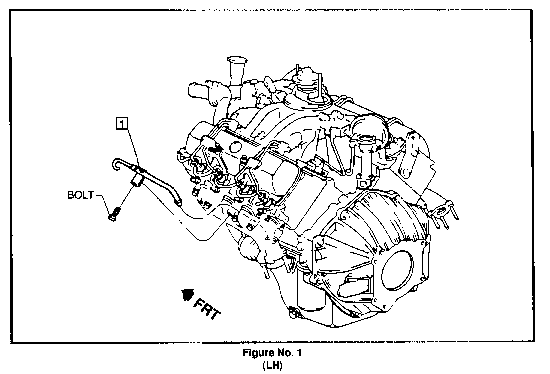
2. Remove oil dipstick tube assembly (1). Refer to Figure 1 LH.
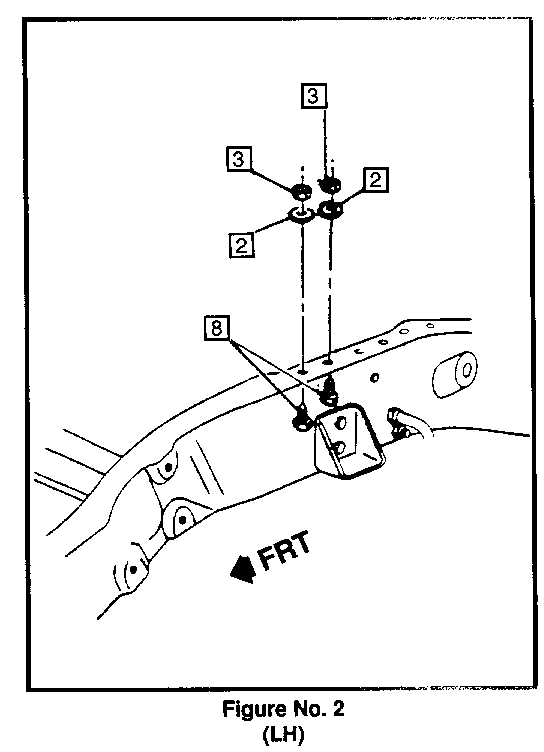
3. Remove existing nuts (3), washers (2), and bolts (8). DISCARD. Refer to Figure 2 LH.
4. Weld crack using welding procedure, if necessary.
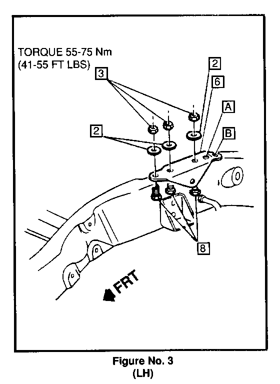
5. Position bracket (6) on top flange area of frame rail. Refer to Figure 3 LH.
6. Install new bolts (8), washers (2), and nuts (3). Torque nuts (3) to 55-75 Nm (41-55 lbs/ft). Refer to Figure 3 LH.
7. Using bracket (6) as a template, drill through top of frame rail at holes A and B with 13/32" diameter high speed drill. A right angle drive is suggested. Refer to Figure 3 LH.
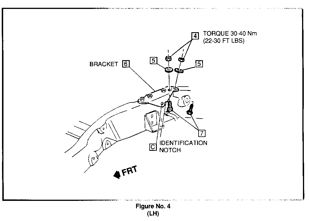
8. Install new bolts (7), washers (5), and nuts (4). Torque nuts (4) to 30-40 Nm (22-30 lbs/ft). Refer to Figure 4 LH.
9. Using bracket (6) as a template, enlarge hole C with 15/32". diameter high speed drill. Access through left-hand wheel opening is suggested. Refer to Flgure 4 LH.
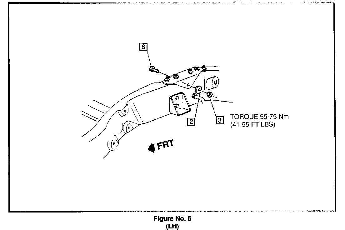
10. Install new bolt (8), washer (2), and nut (3). Torque nut (3) to 55-75 Nm (41-55 lbs/ft). Refer to Figure 5 LH.
11. Install oil dipstick tube (1). Refer to Figure 1LH.
12. Reconnect batteries.
IMPORTANT: The left-hand frame bracket can be identified by a notch located rearward of the web hole (hole C). Refer to Figure 4 LH.
General Motors bulletins are intended for use by professional technicians, not a "do-it-yourselfer". They are written to inform those technicians of conditions that may occur on some vehicles, or to provide information that could assist in the proper service of a vehicle. Properly trained technicians have the equipment, tools, safety instructions and know-how to do a job properly and safely. If a condition is described, do not assume that the bulletin applies to your vehicle, or that your vehicle will have that condition. See a General Motors dealer servicing your brand of General Motors vehicle for information on whether your vehicle may benefit from the information.
