Refer to
DLC, MIL, I/P (5.0L/5.7L)
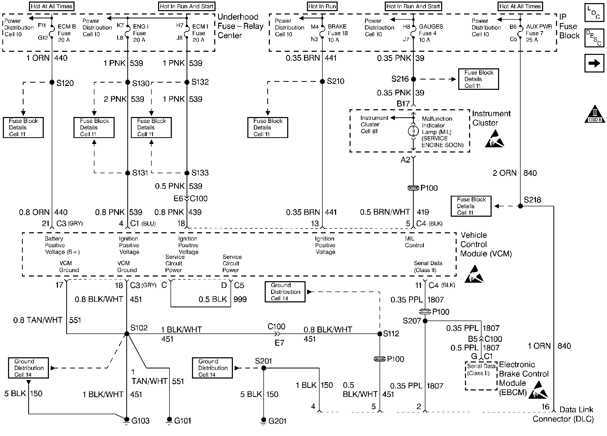
.
Circuit Description
There should always be a steady MIL when the ignition is ON and the engine is stopped. The battery supplies voltage to the lamp. The VCM turns ON the lamp by grounding the MIL control circuit whenever a DTC sets and the DTC meets the requirements for illuminating the MIL.
Test Description
The numbers below refer to the step numbers on the diagnostic table.
Step | Action | Value(s) | Yes | No |
|---|---|---|---|---|
1 | Was the Powertrain On-Board Diagnostic (OBD) System Check performed? | -- | ||
With a test light connected to ground, probe the DLC connector battery feed circuit (Pin 16). Is the test light ON? | -- | |||
With a test light connected to B+, probe the DLC connector (Pins 4 and 5). Is the test light on for both circuits? | -- | |||
4 | Check for proper operation of the cigarette lighter. Does the cigarette lighter operate properly? | -- | ||
5 | Verify the proper operation of the scan tool with a known good vehicle with the same equipment and controller. Does the scan tool communicate with a known good vehicle? | -- | ||
6 |
Is the voltage on the serial data line less than the specified value? | 7.0 V | ||
7 | With the DVM connected to ground, check the serial data line at the DLC connector (Pin 2). Is the voltage less than the specified value? | 1.0 V | System OK | |
8 |
Is the resistance less than the specified value? | 10 ohms | ||
9 |
Is the resistance less than the specified value? | 10 ohms | ||
10 | Repair the open in the serial data circuit. Is the action complete? | -- | -- | |
11 | Repair the open in the battery feed circuit to the DLC connector (Pin 16). Refer to Wiring Repairs in Engine Electrical. Is the action complete? | -- | -- | |
12 |
Is the action complete? | -- | -- | |
13 | Repair the cigarette lighter. Is the action complete? | -- | -- | |
14 |
Is the action complete? | -- | -- | |
15 | Repair short to ground in the serial data line. Refer to Wiring Repairs in Engine Electrical. Is the action complete? | -- | -- | |
16 | Repair the short to voltage in the serial data line. Refer to Wiring Repairs in Engine Electrical. Is the action complete? | -- | -- | |
17 | Replace the VCM. Important: the new VCM must be programmed. Refer to VCM Replacement/Programming (With KS Calibration PROM) Is the action complete? | -- | -- | |
18 |
Does the engine start and continue to run? | -- | ||
19 |
Are any DTCs displayed? | -- | Go to The Applicable DTC Table | |
20 | Using the scan tool, select the Capture Info and the Review Info. Are any DTC displayed that have not been diagnosed? | -- | Go to The Applicable DTC Table | System OK |
