INSUFFICIENT A/C COOLING DIAGNOSIS AND REPAIR

G VAN A/C PERFORMANCE
VEHICLES AFFECTED: 1985-1988 G VANS EQUIPPED WITH RPO C60 AND C69 ----------------- AIR CONDITIONING
Some owners of 1985-1988 G Van models may comment about insufficient cooling from the A/C system. If following the diagnostics found in the Light Duty Service Manual, Section 1B, does not address this condition, one or more of the following additional procedures can be performed at the dealer's descretion to enhance the a/c performance:
1. Replace current A/C condenser with a larger fin area condenser. (This can affect outlet air temperature performance by 2-3 degree F.)
2. Install a heater water by-pass valve in the heater inlet hose. (This can affect outlet air temperature performance by up to 5 degrees F.) This valve prevents hot engine coolant from circulating through the heater core while the A/C is being used.
3. Replace air inlet recirculating door assembly with a new door with new sealing. (This can affect outlet air temperature performance by 3-5 degrees F.) The new door reduces the amount outside air that has to be cooled while in the max a/c position.
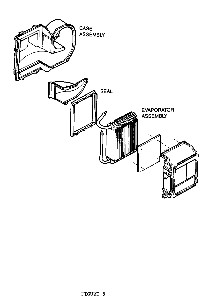
4. Replace case seal on evaporator core case. If accumulator can be moved by light hand pressure, this may indicate an undersized case seal. An undersized seal will allow air to bypass the evaporator and not be cooled.
Notice: Vehicles built after the following VIN breakpoints (B.P.) are equipped with the new condensers and the air inlet recirculating door:
ENGINE PART NO. PART NAME VIN B.P. ------ -------- --------- -------- 4.3, 5.0, 5.7 52450903 Condenser Chev J4125958 GMC J4507802 Chev J7143311 GMC J7518794
LH6 (6,2L Diesel) 52450904 Condenser Chev J4128310 LL4 (6.2L Diesel) GMC J4509065 LT9 (5.7L Gas) Chev J7143311 GMC J7518794
ALL 52450931 Air Inlet Chev J4126103 Recirculating Door GMC J4507847 Chev J7143311 GMC J7518794
Condenser Replacement
Replacement condenser assemblies are direct replacements for the existing condensers and are used as follows:
1985-1986 On all engines, 52450904 condenser replaces 3057628 condenser.
1987-1988 52450903 condenser replaces 3091057 condenser on LB4 engines (gas V6, 4.3L) ; L03 engines (gas V8 5.0L); L05 engines (gas V8, 5.7L).
52450904 condenser replaces 3057628 condenser on LH6 engines (diesel 8 cylinder, 6.2L); LL4 engines (diesel 8 cylinder 6.2L heavy duty); and LT9 engines (gas V8 heavy duty 5.7L (350).
Service Procedures
I. CONDENSER REPLACEMENT
Follow procedure described in Section 1B of the G Van Service Manual.
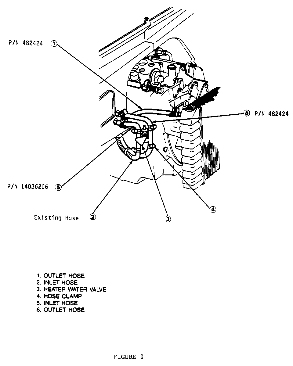
II. HEATER WATER BY-PASS VALVE INSTALLATION (Figure No. 1)
1. Drain radiator. 2. Remove air cleaner inlet tube. 3. Remove heater hose (1) and discard. 4. Remove heater hose (2) from heater core and install at inlet connection of heater water by-pass valve (3) and tighten hose clamp (4).
Notice: All hose clamps removed during valve installation should be discarded and replaced with new hose clamps.
5. Install new 5/8" preformed heater hose (5) from heater water by-pass valve to heater core (cut to length). 6. Install new 3/4" preformed heater hose (6) from heater water by-pass valve to heater core (cut to length). 7. Install new 3/4" preformed heater outlet hose (1) from heater water by- pass valve to radiator (cut to length). 8. Wrap plastic wiring harness around heater hose (1) to eliminate kinking and chafing. 9. Band strap heater hose (2) to heater hose (1) as shown so hoses do not rub edge of radiator shroud. 10. Tighten all hose clamps.
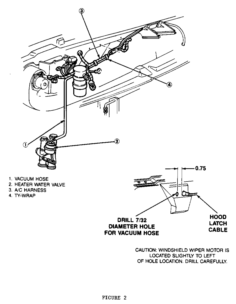
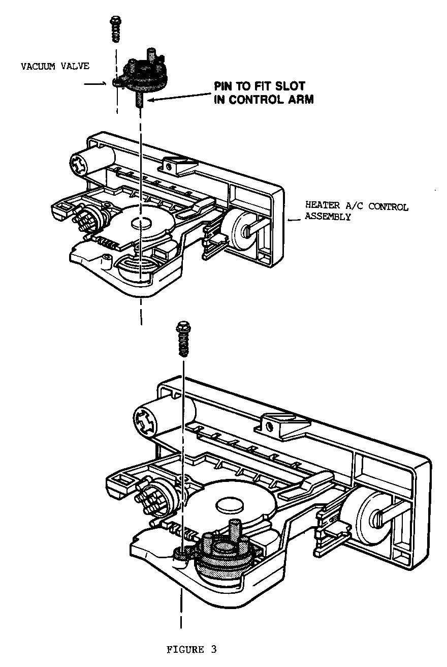
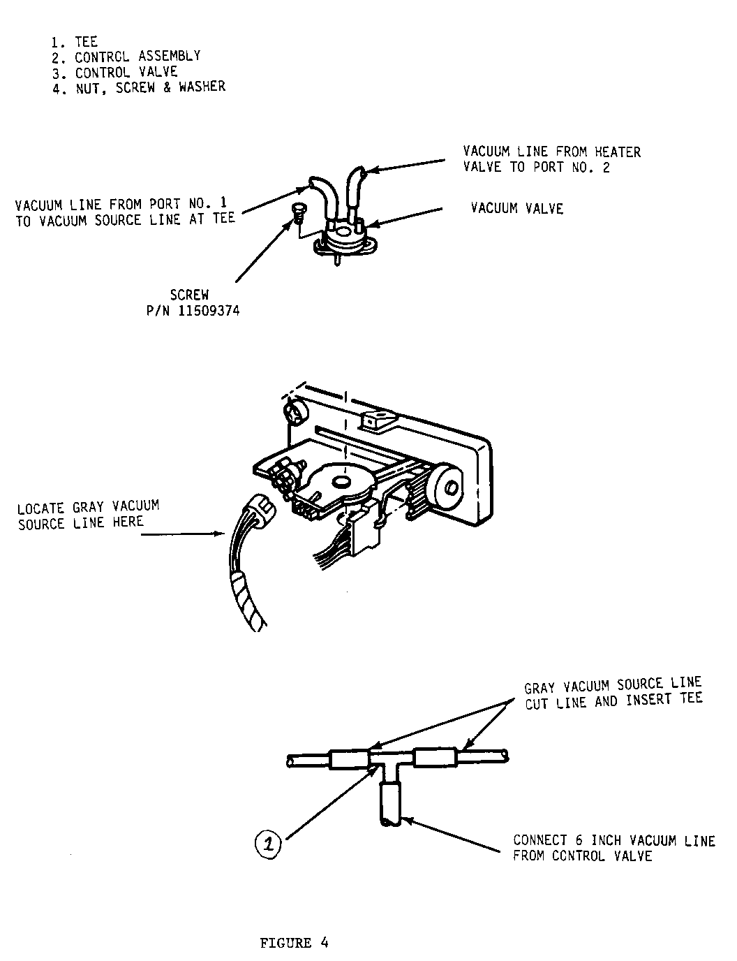
IIA. VACUUM VALVE INSTALLATION (Figures No. 2, 3, and 4)
1. Drill a 7/32" diameter hole in dash wall next to hood latch cable (Figure No. 2) and deburr edges of hole. 2. Install vacuum hose (1) on heater water by-pass valve (2) and route with A/C harness (3) to hole in dash. Band strap (4) hose to harness as shown. Apply sealer around hose as necessary to seal. 3. Remove engine cover and instrument panel lower extension extension for next step. 4. Remove instrument cluster trim plate. 5. Remove HVAC control assembly (Figure No. 3) and slide assembly out of dash sufficiently to gain access to rear of the unit. 6. Install vacuum valve on heater control assembly (Figure No. 3). Slide one mounting ear on valve under the slot on control assembly. Install and tighten screw in opposite ear. (Note: Pin on bottom of vacuum valve must fit into slot on the temperature control arm) 7. Locate gray colored vacuum source line at A/C control assembly (Figure No. 4). 8. Cut gray vacuum source line and insert vacuum tee (1) (Figure No. 4). Attach 6" long vacuum line from vacuum tee to vacuum valve inlet port 1. Attach vacuum ho0307se from heater valve to vacuum valve outlet port 2 (Figure No . 4) . Notice: Port numbers are identified on valve. 9 Reinstall control assembly in dash. 10. Reinstall instrument cluster trim plate. 11. Reinstall engine cover and instrument panel lower extension. 12. Refill radiator with coolant. 13. Run engine and check for coolant leaks. 14. Place temperature control arm in high heat position, check the position of the lever on the heater water by-pass valve. It should be in the extended position. Place control selector in the full cold position and recheck valve. Lever should be in the retracted position. 15. Shut off engine and reinstall air cleaner inlet tube.
III. AIR INLET RECIRCULATING DOOR REPLACEMENT (Figure No.4)
A. Removal
1. Drain radiator. 2. Disconnect battery ground cable. 3. Remove engine cover. 4. Remove steering column filler panel and and remove panel. 5. Remove steering column support bracket and allow column to drop for clearance. 6. Remove righthand sun visor. 7. Remove righthand pillar post molding (if so equipped). 8. Remove upper instrument panel support bracket. 9. Raise and support right side of instrument panel. 10. Remove R.H. heater duct. 11. Remove L.H. heater duct. 12. Remove recirculating air door actuator. Remove and rotate actuator to unhook actuator arm from valve. 13. Disconnect 2 heater cables and clamps, and 4 vacuum hoses to heater and recirculating door actuators. 14. Remove front heater valve actuators and remove actuators. 15. Remove defroster duct to heater and lift duct. 16. Loosen clamps and disconnect heater inlet and outlet hoses. 17. Remove heater to cowl and remove heater from vehicle. 18. Remove air recirculating door to cowl. 19. Remove door and discard. Retain gasket.
B. Installation
1. Remove actuator from new door. 2. Install new door and gasket. Secure with 6 screws. 3. Reverse removal procedure.
IV. EVAPORATOR CORE CASE SEAL REPLACEMENT (Figure No.5)
1. Follow evaporator core replacement procedure found in Section 1B of the Service Manual.
Notice: Complete evaporator core removal is not required. Removal of the core case assembly will allow access to the seal.
Use the most applicable labour operation from the Canadian Labour Time Guide.
PARTS INFORMATION
Part Number Description Quantity ----------- ----------- -------- 7897420 . . . . Vacuum Control Valve 1 14044414. . . . Heater Water By-Pass Valve 1 52450903. . . . Condenser Assembly (1987-1988) 4.3L, 5.0L 1 and 5.7L 52450931. . . . Air Inlet and Recirculating Door Assembly 1 3053203 . . . . "O" Ring, Condenser Inlet 1 3093111 . . . . "O" Ring, Condenser Outlet 1 482424. . . . . Pre-formed Heater Hose, 3/4 Inch 2 14036206. . . . Pre-formed Heater Hose, 5/8 Inch (Cut to Length) 1 3035292 . . . . Seal, Evaporator Core 1 11509374. . . . Screw 1 52450904. . . . Condenser Assembly - 1985-86 All Engines, 1 1987-88 6.2L Diesel and 5.7L Heavy Duty LT9 Engines
No Part Numbers (Procure Locally)
Hose, 3/32 Inch ID Vacuum (72 Inch) 1 1/8 x 1/8 x 1/8 OD Tee, Vacuum Hose 1 Hose Clamp (#8 1/2 Inch - 1 Inch) 7 Bandstrap (Tie Wrap) 8 Inch 5
General Motors bulletins are intended for use by professional technicians, not a "do-it-yourselfer". They are written to inform those technicians of conditions that may occur on some vehicles, or to provide information that could assist in the proper service of a vehicle. Properly trained technicians have the equipment, tools, safety instructions and know-how to do a job properly and safely. If a condition is described, do not assume that the bulletin applies to your vehicle, or that your vehicle will have that condition. See a General Motors dealer servicing your brand of General Motors vehicle for information on whether your vehicle may benefit from the information.
